Table 2-17. channel b dam calibration settings -19, Dam) c – AMETEK SL Series Software User Manual
Page 27
Elgar Electronics Corporation
Calibration Procedure
2.3.3
D
IGITAL
C
URRENT
M
ETER
(DAM) C
ALIBRATION
, C
HANNEL
B
Make the appropriate connections per
DAM, Channel B
1.
Set the DC power supply to +5VDC to input terminal.
2.
Set the load level setting for the model being calibrated, as shown in
Setting column of Table 2-17.
3.
PRESS OFF (press PRES key until its LED is not lit), so that the DAM
is in Measurement mode and not in Preset mode.
4.
LOAD ON (press LOAD key until its LED is lit); adjust using
keys
until the DMM Reading matches the value in DMM Reading column of
Table 2-17.
5.
Scroll to next item (press
) and repeat steps 1 through 4 for each
item through Item 12.
6.
Repeat Steps 1 through 5 for all calibration parameters, Items 9
through 12 (press
three times to return to Item 9) until no further
adjustments are necessary for the DMM reading to match the value in
the DMM Reading column of Table 2-17.
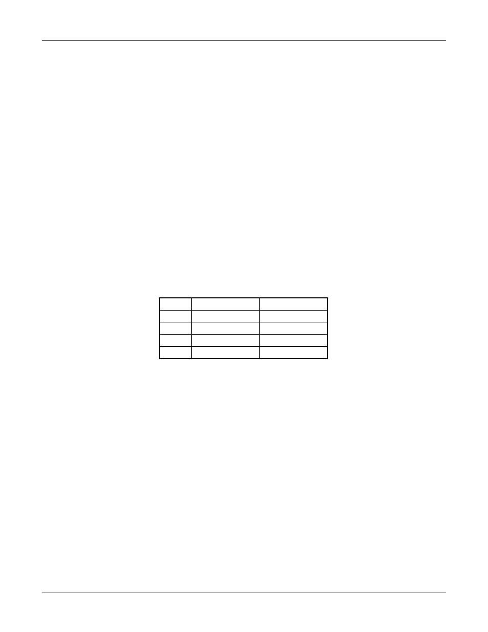
ITEM Setting DMM
Reading
9
0.0000 A
0.000 A
10
1.500 A
6.002 A
11
0.0000 A
0.000 A
12
5.000 A
20.00 A
Table 2-17. Channel B DAM Calibration Settings
for SLD-60-20-102 and SLD-80-20-102
7.
Scroll to next calibration parameter, Item 13 (press
).
SLD Calibration Manual
2-19