Standard verification and calibration procedure, Current mode, Tandard – AMETEK SFA Series User Manual
Page 54: Erification and, Alibration, Rocedure, Current mode -2, Figure 4-1. precision current shunt -2
Verification and Calibration
Sorensen SFA Series
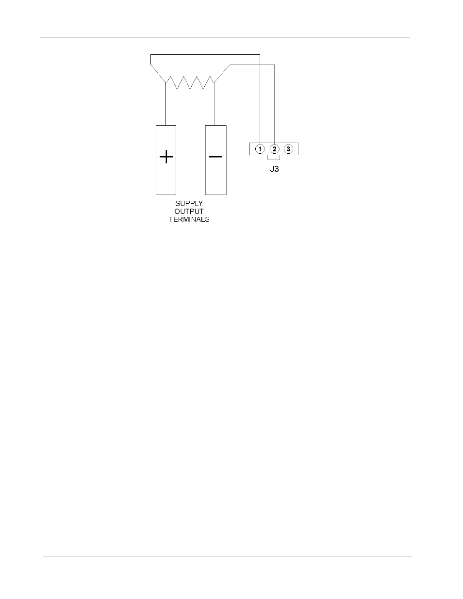
SHUNT
Figure 4-1. Precision Current Shunt
4.2
STANDARD VERIFICATION AND CALIBRATION
PROCEDURE
All calibration potentiometers can be adjusted through access holes in the top
cover of the SFA Series unit. It is not necessary to remove the top cover to
perform the calibration procedures.
4.2.1
C
URRENT
M
ODE
1. Set the SFA Series unit to operate in remote current programming
mode using an external 0-5 Vdc voltage source as shown in Figure 3–6
in Section 3.3 Remote Current Programming.
2. Attach a precision meter across the shunt Kelvin terminals.
3. Attach a precision meter in parallel with the voltage programming
source.
4. Set the voltage source to 0.0V ± 1mV.
5. Apply AC power and verify the current mode indicator is illuminated.
6. Verify the unit is set to 0A ± 0.8% of full-scale output. If necessary,
adjust R55 for zero current through the shunt. (See Figure 4-2.)
7. Set the programming voltage to 5.0V ± 1mV.
8. Verify the unit is set to 100% ± 0.8% of full-scale output current. If
necessary, adjust R69 for 100% of full-scale current on the shunt.
9. Set the programming source for 0.5V ± 1mV.
4-2
M550292-01 Rev G