See table 3–1 for, See table 3–1 for individual pin descriptions, Onnector's pin-out diagram, and table 3–1 – AMETEK SFA Series User Manual
Page 44
Operation
Sorensen SFA Series
Designator
Schematic
Symbol
Electrical
Chars.
Functional Description
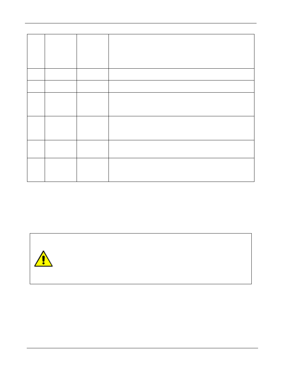
20 Not
Used
21 Not
Used
22
IP RES
*
~ 10.8V
compliance
1 milliamp current source for remote current programming
using resistance. 0-5k ohm resistor referenced to common
will program the output from 0-100%.
23 IP
RTN
Zin ~ 10k
Ω
Current programming return. Used with J1-10, J1-16 or J1-22
and must be referenced to or within ±3V of the circuit
common.
24
COM
†
-
Circuit common. Same potential as the negative output
terminal.
25 IP
RTN
Zin ~ 10k
Ω
Current programming return. Used with J1-10, J1-16 or J1-22
for remote current programming and must be referenced to or
within ±3V of the circuit common.
Table 3–1. ANALOG CONTROL Connector (J1), Designations and Functions
†
Control ground is isolated from power ground with the isolated analog control (option).
See Section 3.2.5.1
*
Signals not available with isolated analog control (option).
CAUTION!
If standard analog programming is used, note the programming return (J1-6 &
J1-24) is at the same potential as the negative output terminal of the power
supply. Observance of return connections should be made with respect to input
programming signal equipment. Improper connection may result in ground loops
and as a result internal power supply damage may occur. (Output current then
flows to chassis by means of external connection to the J1 common (J1-6 &
J1-24)).
3-10
M550292-01 Rev G