AMETEK SFA Series User Manual
Page 42
Operation
Sorensen SFA Series
CAUTION!
This option is not intended to allow operation of the power supply at excessive
voltages. Refer to Section 2 INSTALLATION for maximum terminal voltages.
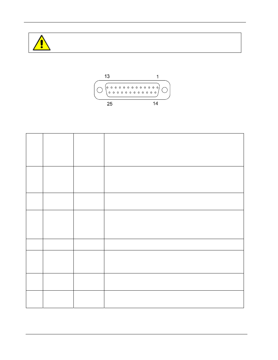
Following are Figure 3-4 with the connector's pin-out diagram, and Table 3–1
with ANALOG CONTROL connector designations and functions:
Figure 3-4. ANALOG CONTROL Connector (J1) Pin-out
Designator
Schematic
Symbol
Electrical
Chars.
Functional Description
1
ISO
ON/OFF
Zin ~ 6 k
Ω
Isolated remote on/off. Externally supplied AC/DC voltage source
for on/off control. A positive (+) 12 to 240 VAC or 6 to 120 VDC
voltage will turn on the supply. This input control is optically isolated
from the power supply circuit up to 500 VDC. See Section 3.5.
2 ISO
RTN
—
Isolated circuit return used with isolated on/off control
J1-1 and J1-14.
3
REM OC
SET
Zin ~
20 k
Ω
Remote overcurrent set. A remote signal sets the overcurrent
trip level. 0-5.5 VDC = 0-110%. Apply a 10.5 VDC to 13.3
VDC signal for 4 seconds to reset an OCP condition. See
Section 3.6.
4 Not
Used
5 ON/OFF
Must sink
~1mA to
enable
Remote on/off. Switch/relay contacts or a direct short
between this terminal and circuit common turns on the unit.
6
COM
†
-
Circuit Common. Same potential as the negative output
terminal.
7 I
MON
Zout ~
100
Ω
Output current monitor. 0-10 VDC equals 0-100% rated current.
Minimum load resistance 10k
Ω.
3-8
M550292-01 Rev G