AMETEK SFA Series User Manual
Page 37
Sorensen SFA Series
Operation
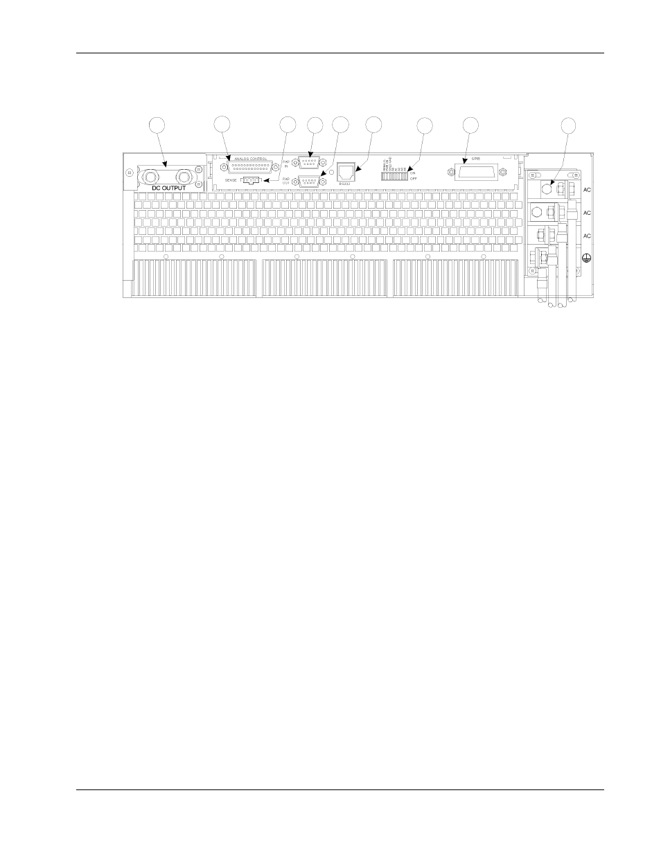
Refer to Figure 3-2 and the corresponding descriptions below for an explanation
of rear panel connectors.
18
17
16
15
14
13
11 12
10
Figure 3-2. Rear Panel Connectors (3U model shown)
10
DC OUTPUT: Positive (+) and negative (–) outputs. Threaded studs for 5-15kW models; bus bars
for 20-30kW models.
11
ANALOG CONTROL Connector (J1): I/O connector for input programming and analog
output monitoring signals as well as status indication and remote shutdown signals.
See Table 3–1 for individual pin descriptions.
12
SENSE Connector (J3): Input connector for load voltage sensing to provide a more
accurate voltage measurement for remote voltage readback and front panel voltage
meter display (see Section 3.4).
13
PARALLEL IN Connector: Allows master/slave configuration of up to five units when
connected to another unit’s PARALLEL OUT connector (see Section 3.8).
14
PARALLEL OUT Connector: Allows master/slave configuration of up to five units when connected
to another unit's PARALLEL IN connector (see Section 3.8).
15
RS232 Connector: Optional RJ-11 connector for remote control.
16
Dipswitch: Eight–position dipswitch to configure an SFA Series unit with an IEEE option.
17
GPIB Connector: Optional connector for remote control.
18
AC Input Bus Bars: Connection for 3-phase AC and Ground.
M550292-01 Rev G
3-3