AMETEK HPD Series GPIB-Multichannel User Manual
Page 45
Installation and Configuration
User Lines
41
User Lines
Connection
(XT, HPD,
XPD)
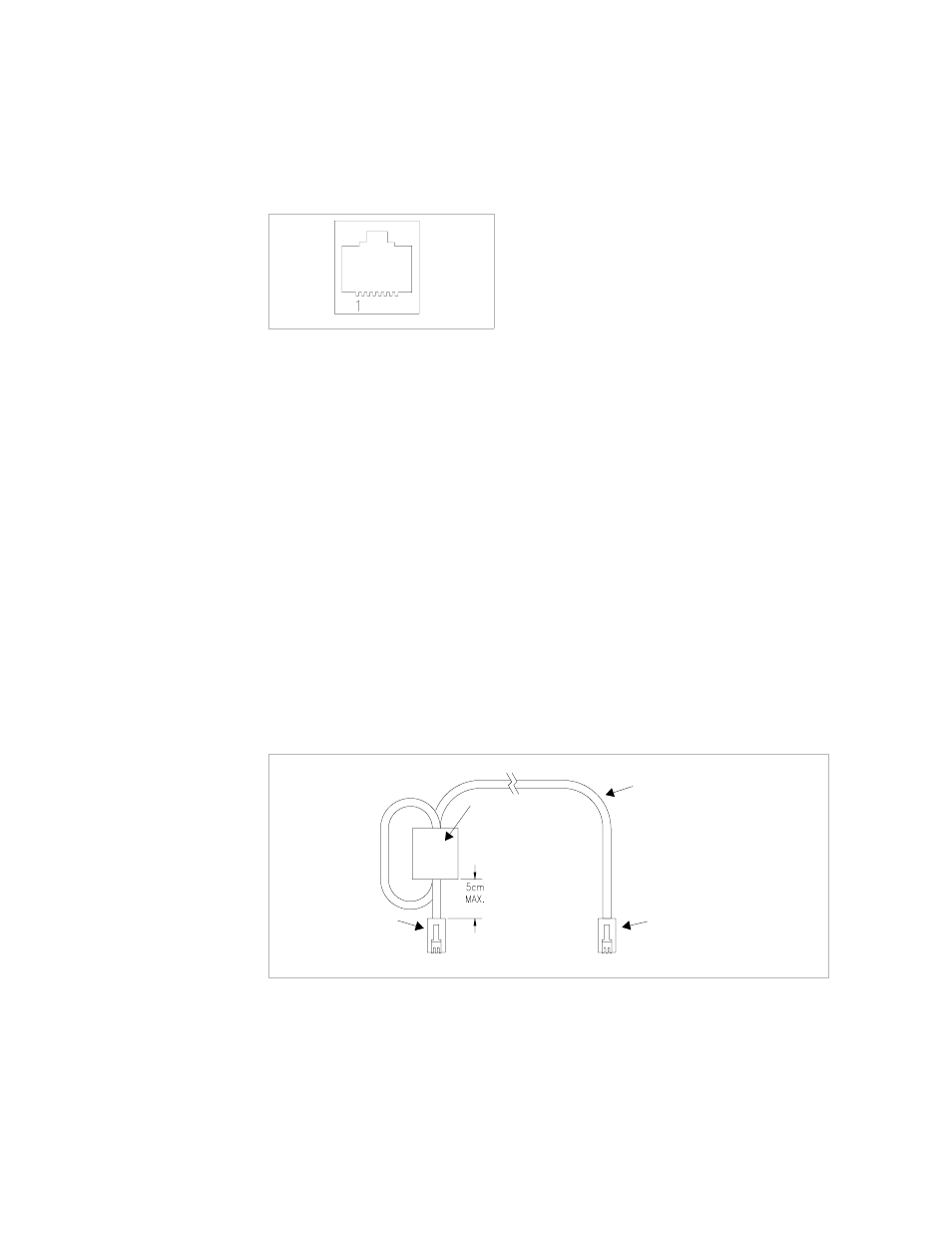
Figure 2.11 User Signals Connector (XT, HPD and XPD)
Use a standard 8-connector RJ45 connector and data cable to connect to the user
lines.
Add a ferrite block to reduce radiated emission. The one inch square ferrite block
with built-in housing clip is packaged and shipped with the power supply interface
card.
To install the ferrite block:
1. Position the block no more than 5 cm (2 in.) from the power supply end of the
user cable.
2. Open the ferrite block housing.
3. Loop the cable through the ferrite block. See
Figure 2.12, “XT, HPD, XPD User
Cable with Ferrite Block” on page 41
.
4. Close the housing clip.
The ferrite block ensures that the power supply system meets radiated emission
requirements for CE mark.
Figure 2.12XT, HPD, XPD User Cable with Ferrite Block
J7 User Cable
Ferrite Block
To User Custom Interface
To J7 Connector
- CW-M (48 pages)
- CW-M Corrected Table 4-2 in (1 page)
- CW-P (62 pages)
- Lx Series (205 pages)
- CW Series Programming Manual (25 pages)
- Ls Series II Programming Manual (242 pages)
- Compact i/iX Series (157 pages)
- Compact IX 2253 (157 pages)
- Compact i/iX Series Software Manual (203 pages)
- ASD Series Quick Start (5 pages)
- ASD Series (120 pages)
- i-iX Series II Programming Manual (226 pages)
- DLM 600W Series Programming Manual (24 pages)
- M131 Programming Manual (99 pages)
- DLM Series (74 pages)
- DLM 600W Series (82 pages)
- BPS Series (153 pages)
- DLM600 Series (16 pages)
- DLM-E 4kW Series Programming Manual (32 pages)
- DCS-E 1.2kW Series (65 pages)
- M136 (8 pages)
- DCS-E 3kW Series (94 pages)
- CTS 3.0 (166 pages)
- CSW Series (174 pages)
- 2003RP (126 pages)
- 2001RP (131 pages)
- MX CTSH (151 pages)
- MXCTSL Administrator Manual (27 pages)
- MX CTSL (157 pages)
- RS Series (228 pages)
- MX Series Installation Manual (35 pages)
- Ls AC source (2 pages)
- MX15 Series (184 pages)
- Ls Series II (226 pages)
- Lx Series Driver Manual (275 pages)
- MX Series Rev: AY (257 pages)
- iX Series (341 pages)
- i-iX Series II (258 pages)
- GUPS 2400A-108 (36 pages)
- HPD Series (58 pages)
- HPD Series Operation Manual (41 pages)
- PLA-PLW Programming Manual (74 pages)
- ReFlex Mating Connnectors for Controller (3 pages)
- LPDC-16V (4 pages)