Common power plane common ground plane, Unused gates – Zilog EZ80190 User Manual
Page 77
UM014108-0810
Schematic Diagrams
eZ80190 Development Kit
User Manual
73
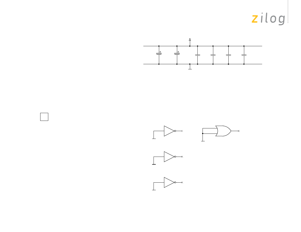
Figure 28. eZ80190 Module Schematic Diagram, #8 of 8—Power Supply
unused gates
GND
V3.3
VDD
VSS
U5D
74LCX32
TSSOP14
12
13
11
C12
22uF
SMT7343
C13
22uF
SMT7343
C14
1nF
0603
C15
100nF
0603
C16
1nF
0603
C17
100nF
0603
PCB1
eZ80190 ethernet module board
98Cxxxx-xxx
U6D
74LCX04
TSSOP14
9
8
U6E
74LCX04
TSSOP14
11
10
U6F
74LCX04
TSSOP14
13
12
no power supply on board
Input: VDD ( = V3.3) = 3.3V –5%
Power: Pmax = tbd
Ptyp = tbd
Current: lmax = tbd
ltyp = tbd
common power plane
common ground plane
See also other documents in the category Zilog Sensors:
- S3F94C8 (11 pages)
- S3F80QB (29 pages)
- S3F8S19 (38 pages)
- Z51F6412 (54 pages)
- Z51F6412 (55 pages)
- Z51F6412 (96 pages)
- EZ80F93 (11 pages)
- Z16F6411 (20 pages)
- Z16F6411 (216 pages)
- EZ80F93 (13 pages)
- ZMOT0BSB (314 pages)
- ZMOT0BSB (582 pages)
- Z8F083A (14 pages)
- Z8F2480 (17 pages)
- Z8F082A (18 pages)
- Z8F082A (15 pages)
- Z8F0822 (17 pages)
- Z8F6423 (83 pages)
- Z8F2480 (19 pages)
- Z8F2480 (18 pages)
- Z8F6423 (18 pages)
- Z8F6423 (27 pages)
- Z8F6482 (50 pages)
- EZ80L92 (79 pages)
- EZ80F91GA (469 pages)
- EZ80F915 (411 pages)
- EZ80F91NAA (34 pages)
- EZ80F91 (41 pages)
- EZ80L92 (40 pages)
- EZ80L92 (26 pages)
- EZ80L92 (10 pages)
- eZ80F92 (87 pages)
- ZUSBOPTS (38 pages)
- ZUSBOPTS (59 pages)
- Z16FMC6 (520 pages)
- Z8FMC16 (26 pages)
- Z16FMC6 (41 pages)
- Z16FMC6 (8 pages)
- Z16FMC6 (26 pages)
- ZMOT1AHH (25 pages)
- ZMOT0BSB (34 pages)
- EZ80F915 (78 pages)
- EZ80L92 (86 pages)
- EZ80F91GA (127 pages)