Vectronics VEC-131K User Manual
Page 23
VEC-131K Owner's Manual
Aircraft Receiver Kit
21
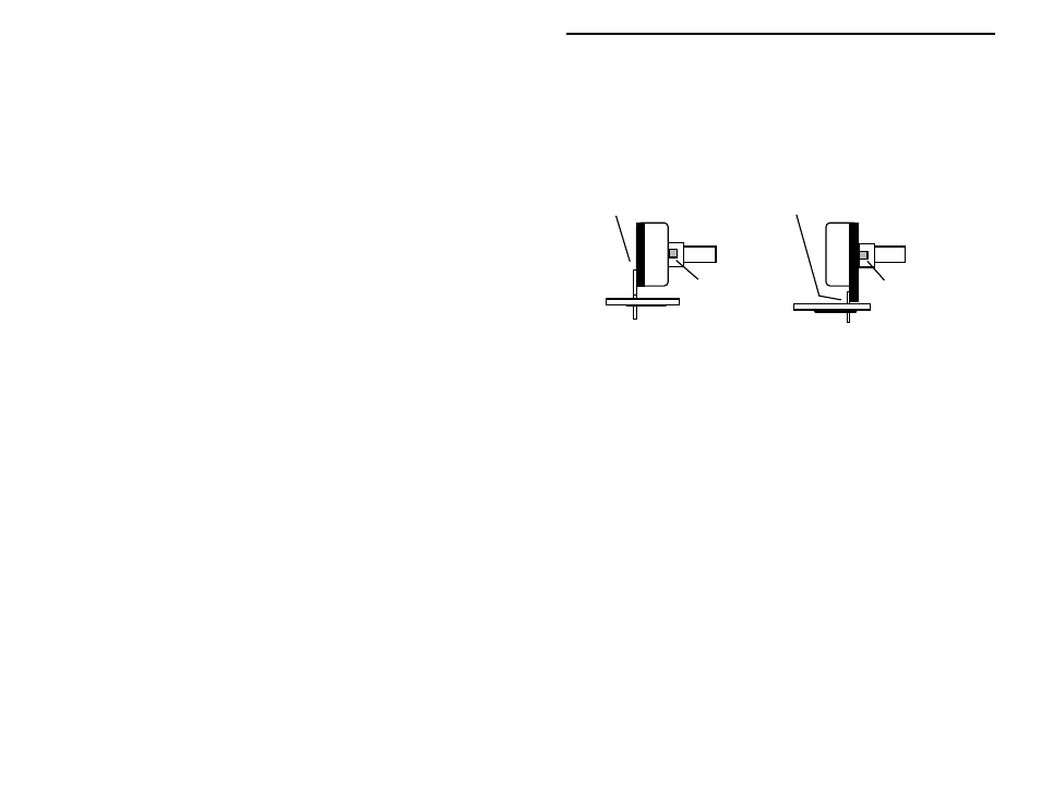
! ! 4. The front-panel controls (tuning, volume) are mounted next. Before
installing these parts, inspect the potentiometer supplied with your kit.
If the pins are located on the front side of the pot, use the front set of
mounting holes on the PC board for installation. If the pins are on the
rear, use the rear set of mounting holes (see below). Also, using side
cutters, remove the key tab from the side of each pot prior to
installation.
Rear pins use rear holes.
Front pins use front holes.
Nip off tab.
Nip off tab.
! !
5. Install a 10Kohm potentiometer at location R18. Insert the
potentiometer leads until the shouldered stops on all three leads are
flush to the PC board. Solder the three pot leads.
! ! 6. Install the remaining 10K ohm potentiometer at R6, following the
procedures used for R18. Solder.
! ! 7. Locate the 3.5 mm stereo earphone jack, then install at J2. The jack
opening faces the board edge. Solder all connections when the jack is
fully seated and level.
! ! 8. Locate the RCA jack. Install at J1, making sure it is fully seated and
level before soldering in place.
The assembly of your kit is finished, and it's time to take a well-earned break!
When you come back, be sure to give your work a close "quality control" (QC)
inspection before moving on.
PC Board Inspection:
! Check all solder connections, looking for unwanted solder bridges or solder
"splashes". Shine a bright light on the solder side of the PC board, and keep
a sharp eye for dull or poorly flowed solder joints. If the solder has adhered
to the component leads, it will form a shiny “cone”; a “donut” like solder
connection may indicate a poor connection.
! Resolder those solder joints that look suspect.