Vectronics VEC-131K User Manual
Page 12
VEC-131K Owner's Manual
Aircraft Receiver Kit
10
STEP-BY-STEP ASSEMBLY INSTRUCTIONS
Before assembling your kit, please take time to read and understand the VEC kit
warranty printed on the inside cover of this manual. Read through the assembly
instructions to make sure the kit does not exceed your skill level. Once
construction is started, the kit is non-returnable. Finally, if you haven't already
done so, please verify that all parts listed in the inventory are included. If
anything is missing or broken, refer to the warranty instructions for replacing
missing or damaged parts. The VEC-131K is an intermediate level kit;
experienced kit builders should expect assembly to average 5 hours.
First, a few notes and comments to help you along. Part designators for
components such as R1, C3, etc., appear on the silk-screened legend on the
component-mounting side of the printed circuit board. These correspond to the
drawing shown in "Parts Placement Diagram" of this manual. The parts are
inserted on the silk-screen side of the board.
Install multilayer and ceramic capacitors so their values are facing the board
edges. Likewise, orient all fixed-resistor color bands in similar directions. Doing
so makes troubleshooting and verifying that no errors were made during
assembly easy.
If you have last minute questions concerning what tools or materials are needed
to assemble this kit, please refer back to the section entitled "Before You Begin".
In these instructions, when you see the term install, this means to locate, identify,
and insert the part into its mounting holes on the PC board. This includes pre-
bending or straightening leads as needed so force is not required to seat the part.
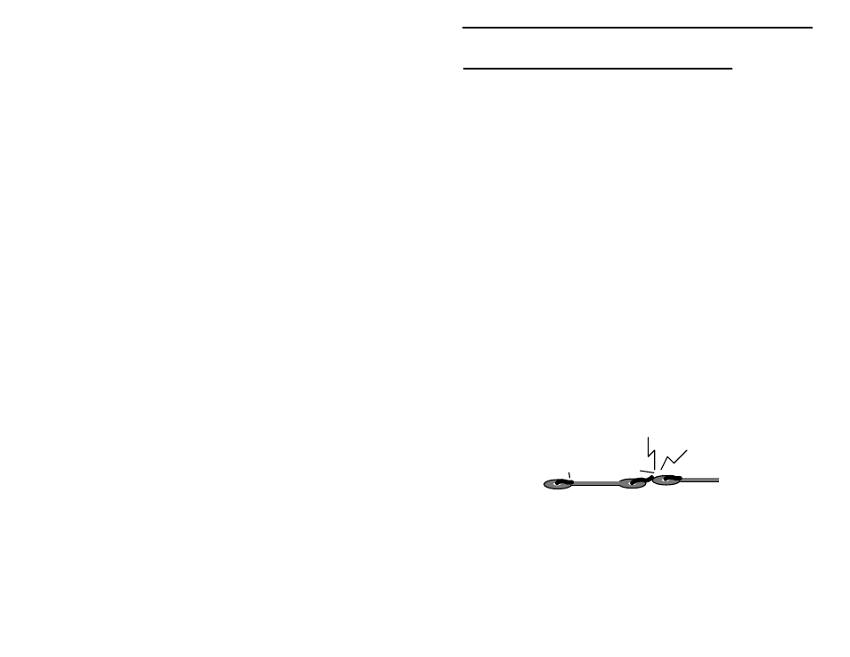
Once a component is mounted, bend each lead over to hold it in place. Use
sharp side-cutters to clip off excess lead length before soldering. Make sure
trimmed leads don't touch other pads and tracks, or a short circuit may result:
Good
Not Good
The term solder means to solder the part's leads in place, and to inspect both (or
all) solder connections for flaws or solder bridges. Nip off excess protruding
leads with a sharp pair of side cutters.
Generally, it's easier to install small close-to-the-board parts first, and then
mount larger stand-up parts second. Delicate parts, such as air-wound coils,
usually go on the PC board last.