Vectronics VEC-131K User Manual
Page 15
VEC-131K Owner's Manual
Aircraft Receiver Kit
13
Phase 3: Installation of Disc Ceramic and Multilayer Capacitors
Important note: All capacitors should be installed with their bodies as close to
the PC board as possible. This is very important in VHF circuits.
! ! 1. Locate the 2.2 pF disc ceramic capacitor. It has a “2.2” marking.
! ! 2. Install the 2.2 pF disc ceramic at silk-screen location C4. Reform the
leads as needed. While holding the capacitor in place, solder both
leads and trim excess lead length.
! ! 3. Find the 4.7 pF disc ceramic capacitor (marked “4.7”). Install and
solder at C2.
! ! 4. Find the 6.8 pF disc ceramic capacitor (marked “6.8”). Install and
solder at C6.
! ! 5. The next capacitor is a 10-pF multilayer style capacitor. This part
may be marked either with a "10" (its actual value in pF) or "100" (a
three-digit "J" code). Find this capacitor.
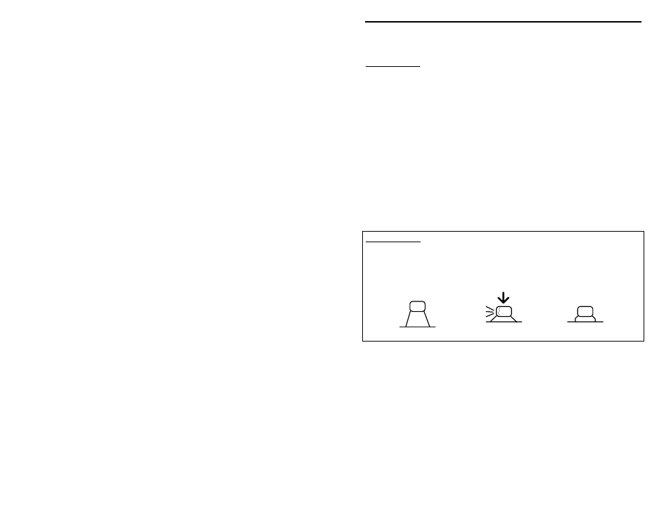
Important Note: A multilayer cap is similar to a surface-mount "chip" capacitor,
except that it has a lead spot-welded onto each end of the capacitor body.
Multilayers have superior radio-frequency operating characteristics, but the lead
welds may fail if the device is over-stressed during installation or removal. For
this reason, never use force to seat a multilayer cap into the PC board. If the
spacing isn't right, preform the leads to the correct spacing before installation!
Incorrect
Ooops!
Correct
! ! 6. Install and solder the 10 pF multilayer at location C1.
! ! 7. Locate the two 18 pF multilayer capacitors (marked "18" or "180").
! ! 8. Install and solder a 18 pF multilayer at location C11.
! ! 9. Install and solder a 18 pF multilayer at C12.
! ! 10. Locate the two 33 pF multilayer capacitors (marked "33" or "330").
! ! 11. Install and solder a 33 pF multilayer at location C3.
! ! 12. Install and solder a 33pF multilayer at C5.