Vectronics VEC-131K User Manual
Page 13
VEC-131K Owner's Manual
Aircraft Receiver Kit
11
Notice that the directions use two sets of check boxes. Check one when a step is
complete and use the other for double-checking your work before operation.
Phase 1: Resistor Installation
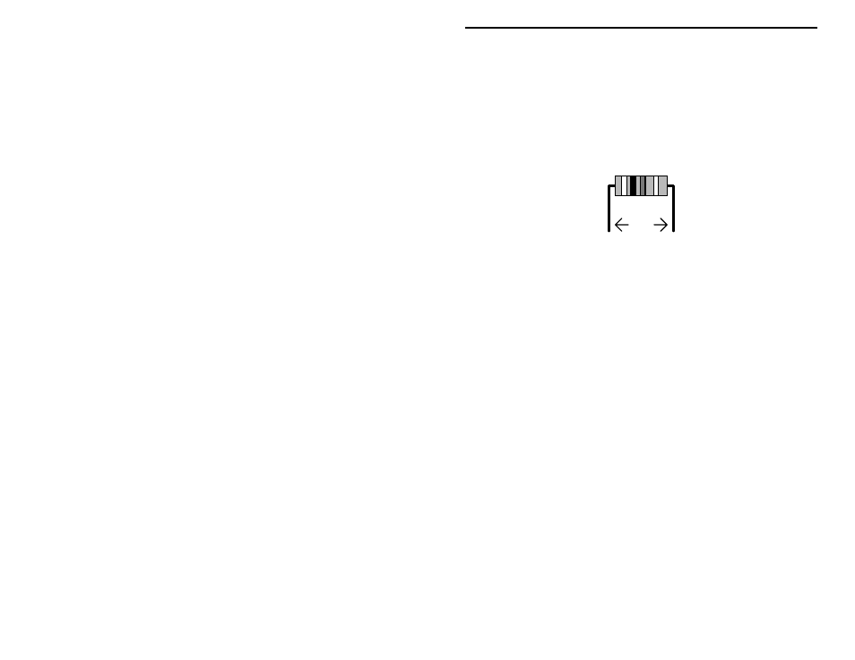
! ! 1. Begin assembly by installing the fixed resistors. Because these are all
5-percent tolerance ending with a fourth gold color band, you need
only specify the first three bands of the color code during the
following steps. All resistor leads should be formed as shown below.
.4"
! ! 2. Locate the 22 ohm resistor (red-red-black). Install and solder at silk-
screen location R23.
! ! 3. Find the 100 ohm resistor (brown-black-brown). Install and solder at
R11.
! ! 4. Locate the three (3) 470 ohm resistors (yellow-violet-brown).
! ! 5. Install and solder a 470 ohm resistor at R2.
! ! 6. Install and solder a 470 ohm resistor at R3.
! ! 7. Install and solder a 470 ohm resistor at R8.
! ! 8. Locate the three (3) 1K (or 1000-ohm) resistors (brown-black-red).
! ! 9. Install and solder a 1K resistor at R9.
! ! 10. Install and solder a 1K resistor at R13.
! ! 11. Install and solder a 1K resistor at R21.
! ! 12. Locate the three (3) 2.2K resistors (red-red-red).
! ! 13. Install and solder a 2.2K resistor at R7.
! ! 14. Install and solder a 2.2K resistor at R12.
! ! 15. Install and solder a 2.2K resistor at R19.
! ! 16. Locate the three (3) 10K resistors (brown-black-orange)
! ! 17. Install and solder a 10K resistor at R15.
! ! 18. Install and solder a 10K resistor at R17.