Vectronics VEC-131K User Manual
Page 17
VEC-131K Owner's Manual
Aircraft Receiver Kit
15
! ! 38. Find the 10.7 MHz ceramic filter. It looks something like a square disc
ceramic capacitor with three pins on the bottom. FL1 is not polarized
and can be installed either way. Install and solder in place at the
designation for FL1.
This completes the installation of all disc and multilayer capacitors. There
should be no “leftovers” remaining, and all PC board locations for these devices
should be filled. Carefully recheck your work for errors and soldering.
Phase 4: Semiconductor Installation
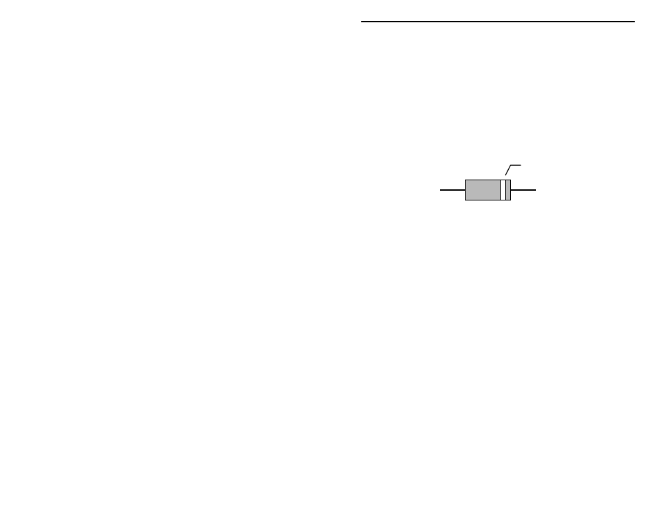
! ! 1. Find the three diodes. Select the two glass bodied devices.
Cathode
1N270, 1N5235B
! ! 2. Take the 1N270 germanium detector, the larger glass diode. The large
black band indicates the “cathode” lead. The body is marked
“1N270”, although you may need a magnifying glass to read it.
! ! 3. Carefully bend the diode leads to align with the holes for D3. Exercise
care—the glass body is fragile and will crack if its leads are over
stressed. Insert the 1N270 into location D3; the cathode lead should
face capacitor C29.
! ! 4. Solder and trim the leads of diode D3.
! ! 5. Take remaining glass bodied diode, it also has a black band indicating
the cathode lead. Form the diode leads and insert at location D2. The
cathode lead faces resistor R8. Diode D2 is a 6.8-volt zener.
! ! 6. Solder and trim the leads of diode D2.
! ! 7. Find diode D1, it is a varactor tuning device. It resembles a plastic
bodied transistor, but only has two leads. The body is marked
“MV2104”.
! ! 8. The body of D1 has a “round” and “flat” side. When inserted into the
PC board, the body position must correspond with the silk-screened
outline shown for D1. Install and solder the MV2104 at location D1.