Vectronics VEC-131K User Manual
Page 22
VEC-131K Owner's Manual
Aircraft Receiver Kit
20
with an Exacto knife and tin the lead. Make sure both leads are clean and
brightly tinned all the way around before attempting to install the coil.
! ! 9. Strip and tin the leads of the 4-turn coil, as illustrated previously.
When both leads are fully tinned, remove it by "unscrewing" the coil
body from the form. Shape as shown and trim leads to 1/2".
! ! 10. Following the above procedure, prepare a second 4-turn coil.
! ! 11. Use the remaining #24 wire to prepare a nine (9) turn coil.
! ! 12. Install one of the 4-turn coils at location L2. You may have to expand
the windings slightly so the leads align with their mounting holes.
Solder and trim.
! ! 13. Install the other 4-turn coil at L3. Solder and trim.
! ! 14. Install the 9-turn coil at L1. Solder and trim.
Phase 7: Completing Construction
! ! 1. Locate the push-button DPDT power switch. Install at SW1,
positioning so the push-rod faces the board edge (shown below).
While holding the switch body flush against the board, solder and trim
the six switch pins.
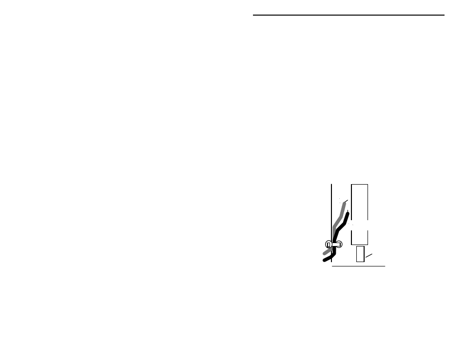
Tie-wrap
black
+
red
SW1
Push-rod
! ! 2. Install the 9-volt battery snap. Insert the red lead at +9V and the black
lead at GND. Solder and trim.
! ! 3. Stress relief is provided to prevent battery leads from flexing and
eventually breaking at their connection point. Find a hole part-way
back on the left edge of the PC board (near SW1). Use the plastic tie-
wrap provided in your kit to secure the battery leads in place (as
shown in the previous diagram). Insert the tie-wrap through the hole,
close it over the wires, and pull tight. Nip off the excess end.