Vectronics VEC-131K User Manual
Page 14
VEC-131K Owner's Manual
Aircraft Receiver Kit
12
! ! 19. Install and solder a 10K resistor at R22.
! ! 20. Locate the three (3) 47K resistors (yellow-violet-orange).
! ! 21. Install and solder a 47K resistor at R5.
! ! 22. Install and solder a 47K resistor at R14.
! ! 23. Install and solder a 47K resistor at R16.
! ! 24. Locate the three (3) 100K resistors (brown-black-yellow).
! ! 25. Install and solder a 100K resistor at R1.
! ! 26. Install and solder a 100K resistor at R4.
! ! 27. Install and solder a 100K resistor at R10.
! ! 28. Find the one 1 Mega ohm resistor (brown-black-green). Install and
solder at R20.
! ! 29. Check that all resistor locations on the PC board are occupied by the
correct value resistor.
! ! 30. Check each solder joint. Look for solder splashes, bridges (a bridge is
where solder has made a connection between two or more points that
should not be connected), or poor solder connections.
Tip: Watch for unwanted bridges between adjacent component pins!
Phase 2: Installation of Jumper Wires
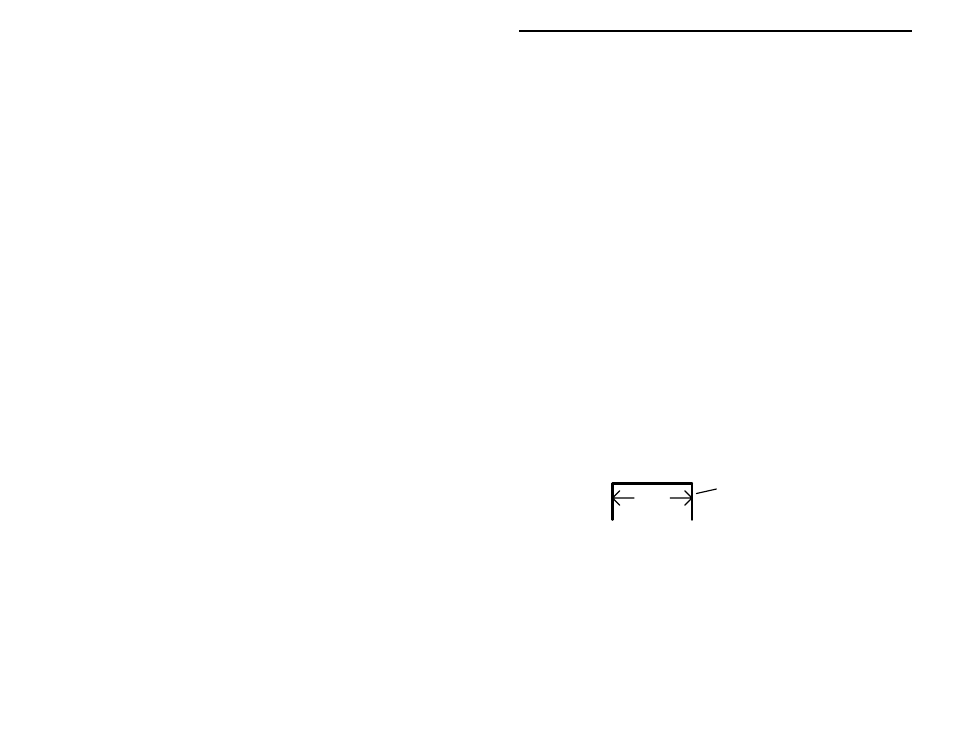
! ! 1. Select three scrap resistor lead ends for use as jumper wires, as shown
below. Use needle-nose pliers to form each one, making sure each
rests flat on the PC board when installed:
span
discarded lead end
! ! 2. Prepare, install, and solder a jumper at JMP1.
! ! 3. Prepare, install, and solder a second wire at JMP2.
! ! 4. Prepare, install, and solder a third wire at JMP3.