Water hose routing – Paxton Superchargers 5.7L Dodge Hemi User Manual
Page 35
1
P/N: 4809650
©2004 Paxton Automotive
All Rights Reserved, Intl. Copr. Secured
11NOV04 v1.0 03DodgeHemi(4809650v1.0)
Section 13
WATER HOSE ROUTING
13. WATER HOSE ROUTING
*** NOTE ***
Make sure to leave the hose slightly long to allow for
engine movement.
A.
Using a 3/4" 90° molded hose, trim 2" off
from the short hose leg, attach the cut end
onto the 3/4" x 1/2" NPT 90° brass fitting on
the passenger side of the supplied heat
exchanger previously installed. Install a sup-
plied 3/4" brass hose mender into the long
end of the hose.
B.
Using a supplied 3/4" 90° molded hose, trim
2" off of the short end, install the short end
onto the 3/4" 90° brass fitting previously
installed in the aftercooler core. Install a
supplied 3/4" brass hose mender into the
long end of the molded hose.
C.
Cut a 55" section of 3/4" hose, connect one
end onto the 3/4" hose mender previously
installed in the molded hose attached to the
aftercooler. Route the hose along the passen-
ger side inner fender, under the radiator, and
connect to the open end of the 3/4" brass
hose mender/elbow hose connected to the
heat exchanger.
D.
Using another 3/4" 90° molded hose trim
2-1/2" off of the short end of the hose,
install the short end onto the outlet of the
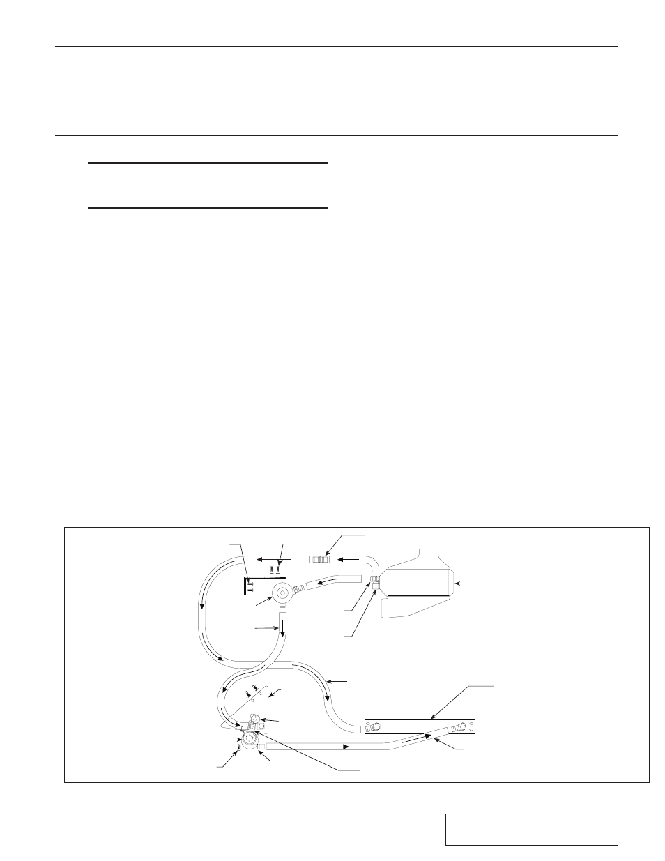
Fig. 13-a
previously installed water pump. Install a
3/4" brass hose mender into the open end of
the hose.
E.
Cut a 27" long section of the supplied 3/4"
hose, attach an end to the open end of the
previously installed brass hose mender.
Attach the open end of the hose to the open
fitting on the supplied heat exchanger, trim
the hose for best fitment.
F.
Cut a 14" long section of the supplied 3/4"
hose, attach one end to the straight fitting on
the aftercooler core, connect the open hose
end to the fitting on the side of the surge
tank, trim the hose length for best fitment.
G.
Cut a 60" long section of the supplied 3/4"
hose, attach one end to the 3/4" x 1/2" NPT
brass fitting previously installed in the bot-
tom of the supplied surge tank. Route the
hose along the passenger side inner fender
and connect the open end of the hose to the
3/4" x 1/2" NPT 90° brass fitting on the top
of the water reservoir, trim the hose for best
fitment.
H.
Secure all hose connections using the sup-
plied nylon hose clamps. Check to ensure all
hose lines are free of kinks, secure hose
lines as needed away from sharp, hot, or
moving objects using the supplied wire ties.
7E010-075 SHEET METAL SCREWS (SECURES
SURGE TANK BRACKET TO FIEWALL)
1/4 x 20 x 1/2 BOLTS 7A250-051
6mm WASHER 7J006-093
3/4 HOSE UNION
BARDED 7P375-075
3/4" HOSE
(7U038-000)
CUT TO FIT
90
° 1/2 NPT TO
4" HOSE BARB
(7P500-026)
SURGE TANK
(8N156-050)
AIR CHARGE COOLER ???
(8PN101-180)
90
° 1/2 NPT TO
4" HOSE BARB
(7P500-026)
3/4" HOSE (7U038-000)
CUT TO FIT
WATERCOOLER (8N006-010)
WATERCOOLER (8N006-010)
90
° MOLDED HOSE ELBOW (7U030-065) CONNECTS FITTING ON BOTTOM
TANK TO INLET OF WATER PUMP
WATER PUMP
(8F001-402)
1/2" SOCKET HEAD CAP SCREW (7A250-050)
INSTALL THROUGH ADEL CLAMP AND INTO
WATER TANK TO HOLD WATER PUMP
WATER PUMP CLAMP (8N010-080)
WATER
RESERVOIR
(8N055-030)
1" NPT HOLE
NOT USED-
HOLE SHOULD
BE BLIND OR
PLUGGED
13.
WATER HOSE ROUTING