Fuel system assembly – Paxton Superchargers 5.7L Dodge Hemi User Manual
Page 25
1
P/N: 4809650
©2004 Paxton Automotive
All Rights Reserved, Intl. Copr. Secured
11NOV04 v1.0 03DodgeHemi(4809650v1.0)
Section 8
FUEL SYSTEM ASSEMBLY
8. FUEL SYSTEM ASSEMBLY
A.
Locate the supplied supplemental fuel sup-
ply assembly 4PCH101-001. Assemble the
supplied fuel pump to the supplied fuel
pump/FMU mounting bracket using the pro-
vided adel clamps and 1/4"-20 bolts, nuts,
washers as shown in Fig. 8-a.
*** NOTE ***
Verify that the fuel pump outlet fitting is a 5/16"
brass barbed fitting and that a copper washer is
installed and the fitting is tight, if the fitting 5/16"
brass barbed fitting has not been installed it will be
necessary to remove the existing fitting from the
fuel pump and install the supplied 5/16" brass
barbed fitting with a copper washer.
B.
Mount the supplied FMU to the fuel pump/
FMU mounting bracket using supplied
10-24 bolts, nuts, and washers. Assemble
per Fig 8-a.
Fig. 8-a
C.
From beneath the vehicle mark two mount-
ing locations on the inner driver’s side frame
rail near the factory fuel lines for the fuel
pump/FMU bracket assembly to mount. Use
the bracket as a template and mount the
bracket using the supplied self-tapping sheet
metal screws to mount the bracket to the
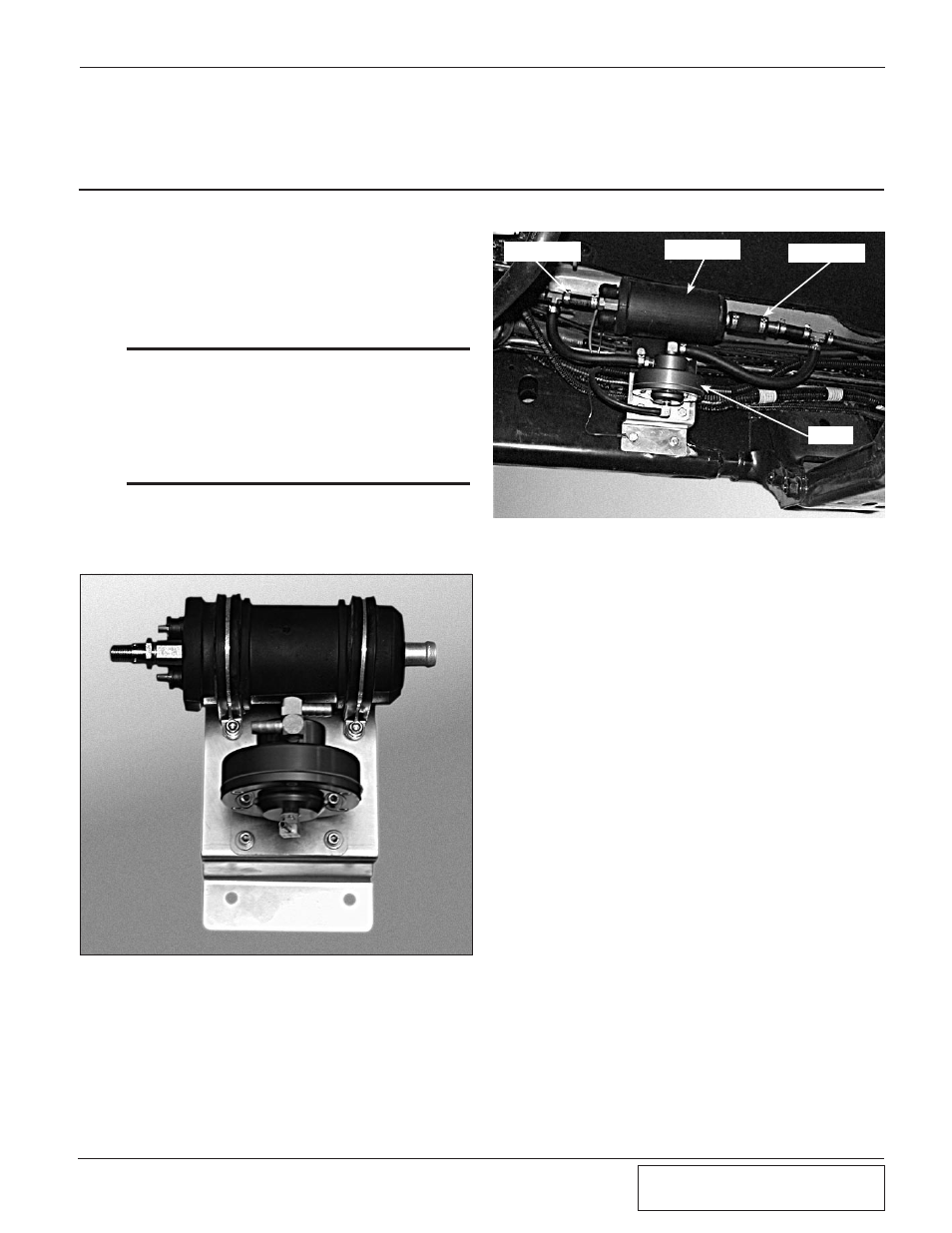
inner frame rail. (See Fig. 8-b.)
Fig. 8-b
D.
Using a 5/16" spring lock disconnect tool
disconnect the flexible fuel line from the
hard line. Attach a length of 5/16" fuel hose
to the outlet of the fuel pump and secure
with a supplied clamp, route the hose to the
open end of the fuel line leading to the
engine. Trim the hose for best fit, install the
supplied male 5/16" fuel line adapter fitting
into the open end of the hose and secure
with a supplied clamp. Attach the male
adapter fitting to the factory fuel line.
E.
Attach a 2-1/2" length of supplied 5/8" fuel
line onto the inlet of the fuel pump, two of
the supplied clamps must be used to secure
this hose onto the fuel pump. Install the sup-
plied 5/8" to 5/16" barbed reducer into the
open end of the previously installed 5/8"
hose, secure using the supplied clamp.
Install a section of 5/16" fuel hose onto the
previously installed barb and secure the end
with a supplied clamp. Route the open end
of the hose to the open end of the fuel line
leading to the vehicle’s gas tank, trim the
hose for best fitment and install a provided
5/16" plastic female fitting into the hose and
secure with a supplied hose clamp. Attach
the supplied female adapter fitting to the
factory fuel line.
F.
Cut the 5/16" fuel hose previously installed
from the supplied fuel pump inlet to the fac-
tory fuel line, install the supplied TEE fitting
at this connection and secure it using two
supplied hose clamps. Attach a length of
FUEL OUTLET
FUEL PUMP
FUEL INLET
FMU
8.
FUEL SYSTEM ASSEMBLY