Paxton Superchargers 5.7L Dodge Hemi User Manual
Page 20
2
P/N: 4809650
©2004 Paxton Automotive
All Rights Reserved, Intl. Copr. Secured
11NOV04 v1.0 03DodgeHemi(4809650v1.0)
H.
With the supplied support brackets assem-
bled using the 5/16" x 18 x 1" bolts, and
washers confirm that the support bracket sits
flush with the cylinder head and engine
block.
I.
Remove the support bracket after confirming
that it sits flush with the head and block.
Using the three 5/16"- 18 x 1" bolts and
washers provided attach the support bracket
to the supercharger mounting plate leave
these bolts loose. Align the supplied support
bracket using the supplied 8mmx120 x 1.25"
bolt and 10mm x 130 x 1.5" bolt. (See Fig.
6-e.)
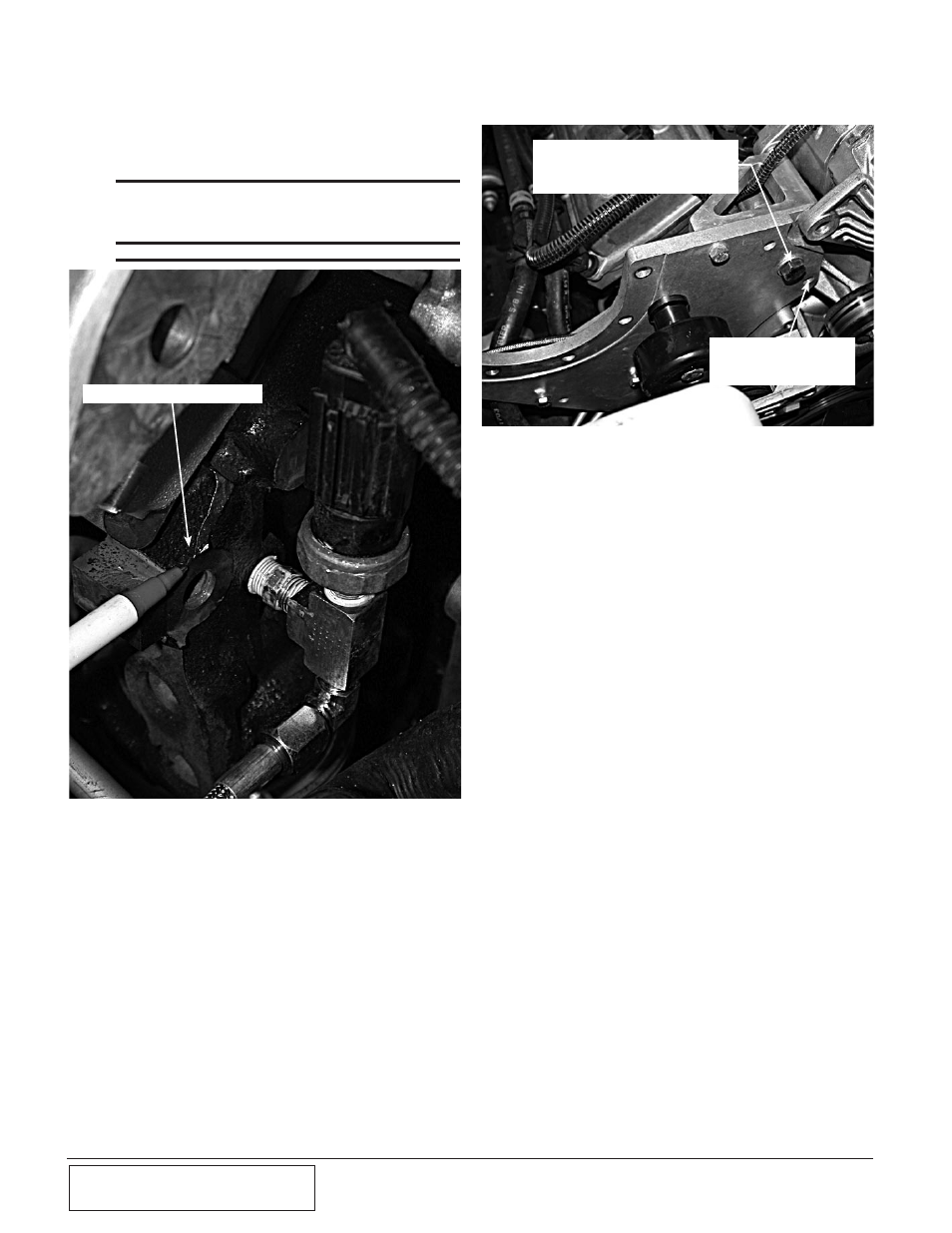
G.
Remove the casting flash from the lower
mounting location using a file or small disc
sander.
*** NOTE ***
Care must be taken to not damage the machined
surface, as this surface is critical to proper mounting
bracket alignment.
Fig. 6-d
CASTING FLASH TO BE REMOVED
Fig. 6-e
J.
Install the supplied supercharger mounting
plate as an assembly using the cylinder head
and the engine block mounting locations.
Leaving the 8mm and the 10mm bolts loose
at this time.
K.
Install the supplied 12mm x 100mm x 1.75"
bolt through the supercharger mounting
plate and into the alternator-mounting boss.
Reattach the ground strap sandwiching it
between the nut and the alternator boss,
secure the bolt with the nut provided leaving
the nut loose at this time.
L.
Install the factory 13mm headed bolt
removed in a previous step. (See Fig. 6-e.)
M.
Locate the supplied supercharger idler pul-
ley, idler pulley stand off and the supplied
7/16" x 3.25" bolt, washers, and nut. Install
the idler pulley and standoff in the location
noted using the supplied hardware. (See Fig.
6-f.)
13mm HEADED BOLT
REMOVED IN AN EARLIER
STEP
INSTALL THE 12mm x 100 x 1.75 BOLT
THROUGH THE ORIGINAL MOUNTING
HOLE IN THE FRONT COVER