Engine control unit installation – Paxton Superchargers 5.7L Dodge Hemi User Manual
Page 27
1
P/N: 4809650
©2004 Paxton Automotive
All Rights Reserved, Intl. Copr. Secured
11NOV04 v1.0 03DodgeHemi(4809650v1.0)
Section 9
ENGINE CONTROL UNIT INSTALLATION
9. ENGINE CONTROL UNIT INSTALLATION
A.
Using a T-15 torx bit remove the two factory
screws securing the panel below the steering
column on the driver’s side of the vehicle
and remove the panel. In a suitable location
in the driver’s compartment under the dash
secure the PECU with the Velcro hook/latch
that is provided.
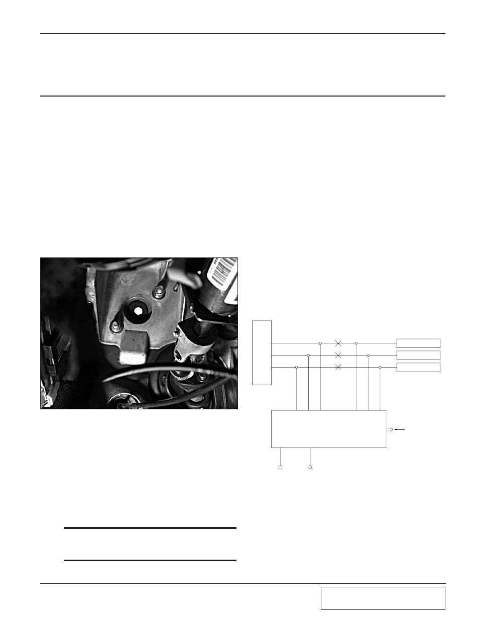
B.
Locate the two 15mm headed bolts that
retain the cover that the clutch actuating
cable would pass through, remove the cover
and drill a 9/16" hole that will allow the
PECU harness and the 5/32" vacuum line to
pass through. Reinstall the cover and route
the PECU wire harnesses and vacuum hose
through the 9/16" opening. (See Fig. 9-a.)
Fig. 9-a
Fig. 9-b
C.
Run the PCEU harness across the firewall
thru the factory wire harness cover to the
Factory engine control unit.
D.
Locate the C2 plug at the factory ECU pin
35, cut the gray/black wire (crank sensor).
Using the connectors provided connect the
gray wire from the PECU to the gray/black
wire leading to the crank sensor. Connect
the gray/black wire from the PECU to the
gray/black wire going to factory ECU plug.
*** NOTE ***
that it is recommended that these and all other con-
nections be soldered.
E.
Locate pin 34 at the C2 plug on the Factory
ECU. Cut the tan/yellow wire (Cam Sensor).
Connect the tan wire from the PECU to the
tan/yellow wire leading to the cam sensor on
the factory ECU. Connect the tan/yellow
wire from the PECU to the tan/yellow wire
leading to the factory ECU plug.
F.
Locate pin 23 at the C2 plug on the factory
ECU. Cut the green/red wire (Map Sensor).
Connect the green wire from the PECU to
the green/red wire leading to the map sensor.
Connect the green/red wire from the PECU
to the wire leading to the factory ECU plug.
G.
Tape up the violet wire, as it will not be
used. Tap the small red wire coming from
the PECU to the C1 plug pin 11. Tap the
small black wire coming from the PECU to
the C1 plug pin 18.
H.
Route the supplied 5/32" vacuum line into
the engine compartment near the brake
booster, it will be connected at a later step.
MAP SENSOR
CAM/SENSOR
CRANK/SENSOR
GREEN/RED
TAN/YELLOW
GREY/BLACK
GREEN/RED
TAN/YELLOW
GREY/BLACK
E
C
U
P
L
U
G
/B
L
A
C
K
P
/N
#
3
5
P
/N
#
3
4
P
/N
#
2
3
C
R
A
N
K
I
N
C
A
M
I
N
M
A
P
/S
E
N
SO
R
TO MANIFOLD
VACUUM/BOOST
G
R
E
Y
/B
L
A
C
K
T
A
N
/Y
E
L
L
O
W
G
R
E
E
N
/R
E
D
G
R
E
E
N
T
A
N
G
R
E
Y
B
L
A
C
K
R
E
D
C
R
A
N
K
O
U
T
C
A
M
O
U
T
M
A
P
/S
E
N
SO
R
O
U
T
C
R
A
N
K
I
N
C
A
M
I
N
M
A
P
/S
E
N
SO
R
IN
PAXTON ENGINE CONTROL UNIT
9.
ENGINE CONTROL UNIT INSTALLATION