Charge cooler installation – Paxton Superchargers 5.7L Dodge Hemi User Manual
Page 29
1
P/N: 4809650
©2004 Paxton Automotive
All Rights Reserved, Intl. Copr. Secured
11NOV04 v1.0 03DodgeHemi(4809650v1.0)
Section 10
CHARGE COOLER INSTALLATION
10. CHARGE COOLER INSTALLATION
A.
Install a supplied reducer sleeve onto the
throttle body, install the aftercooler core into
the reducer sleeve and secure with the sup-
plied hose clamps. Install the supplied 2.75"
x 2" sleeve onto the discharge of the super-
charger and another on the open end of the
aftercooler core previously installed.
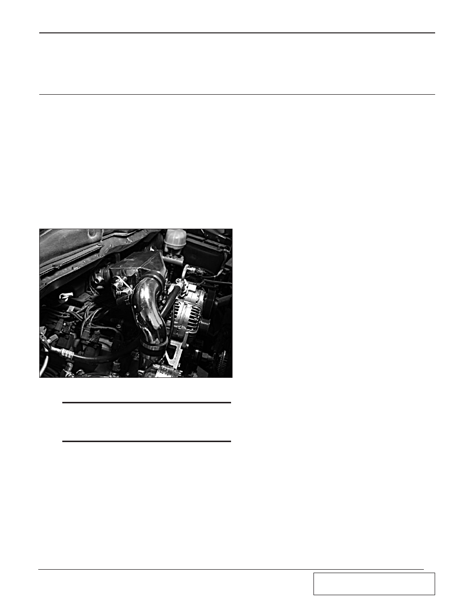
B.
Install the supplied discharge duct between
the supercharger and the aftercooler core
with the welded bung facing the vehicle’s
firewall, secure all connections using the
supplied hose clamps.
Fig.
10
-a
*** NOTE ***
It may be necessary to gently bend the air condition-
ing line to gain clearance between it and the super-
charger discharge.
C.
Install the supplied 3/4" NPT x 90° brass fit-
ting into the lower threaded opening of the
aftercooler core; the fitting must face
towards the firewall of the vehicle. Install
the supplied 1/2" x 3/4" straight brass fitting
into the upper threaded opening in the after-
cooler core.
D.
Install the short end of the supplied 1" 90°
elbow hose onto the bung on the 180° air
inlet duct. Attach a 6" section of 1" hose
onto the bung on the supercharger discharge
duct. Install the supplied bypass valve into
the hose lines per Fig. 10-c.
E.
Attach an end of the supplied 5/32" vacuum
hose onto the vacuum nipple on the previ-
ously installed bypass valve. Route the
length of supplied vacuum hose to the brake
booster mounted on the driver’s side firewall
and secure the hose as necessary using the
supplied wire ties.
F.
Remove the small vacuum cap from the fac-
tory fitting on the vehicle’s brake booster.
Attach the supplied vacuum hose onto the
open port on the brake booster, install a sup-
plied 5/32" brass reducer into the vacuum
line previously installed. Trim the supplied
5/32" vacuum line connected to the bypass
valve for the best fitment and install onto the
open port of the previously installed reducer.
G.
Install a supplied 5/32" brass vacuum TEE
fitting into the bypass valve vacuum line
previously installed and attach the vacuum
line from the FMU to the supplied TEE.
Install another supplied 5/32" brass TEE into
the bypass valve vacuum line; attach the
vacuum hose from the PECU to the previ-
ously installed TEE.
10.
CHARGE COOLER INSTALLATION