3 product deployment – KBC Networks MPEG4 Decoder User Manual
Page 9
Decoder User Manual
Manual-MPEG4_DECA-Rev1206
Copyright © KBC Networks 2011
Page 9 of 29
www.kbcnetworks.com
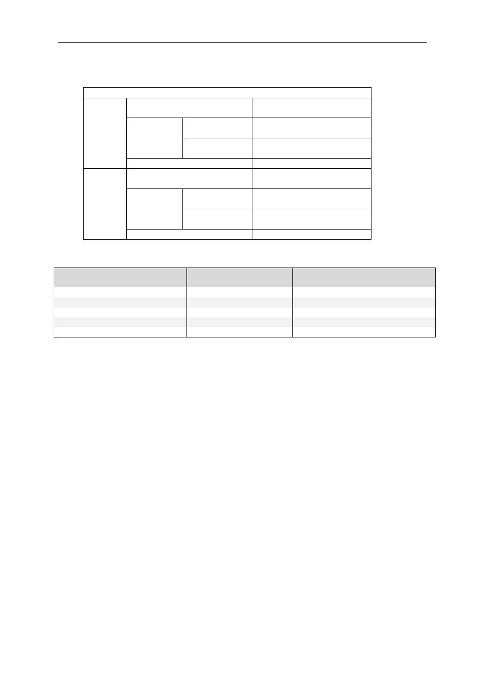
2.2.8 Alarm Input / Output Parameters
2.2.8.1 Voltage Specification
Contact Closure Specification
DI
Connection Design
TTL-compatible logic
levels
Voltage
Trigger
(low)
Logic level 0: 0V ~
0.4V
Normal
(high)
Logic level 1: 3.1V ~
30V
Current
10mA ~ 100mA
DO
Connection Design
TTL-compatible logic
levels
Voltage
Trigger
(high)
Logic level 0: 2.4V ~
5V
Normal
(low)
Logic level 1: 0.1V ~
0.6V
Current
50mA
2.2.8.2 Trigger/Normal State Response
ENC-A-W* Encoder (ENC)
Action
DEC-A-W* Decoder (DEC)
DO1
DO2 DI1
DI2
DO1
DO2
DI1
DI2
ON
ON
ON
ON
Normal State
OFF
OFF
ON
ON
OFF
ON
ON
ON
Short DEC DI1 to GND
GND
ON
OFF
ON
ON
Short DEC DI2 to GND
GND
GND
Short ENC DI1 to GND
ON
OFF
ON
ON
GND Short ENC DI2 to GND
OFF
ON
ON
ON
ON:
Voltage present on port
OFF:
Voltage is 0V
GND:
Alarm trigger device causes DO/DI to short, turning off opposite DO / DI port
Note:
Triggers from default configurations shown. See Decoder Interface settings to
configure other trigger options.
2.3 Product Deployment
2.3.1 Product Default Configuration Settings
2.3.1.1 Operations Manual Defaults
When an encoder is shipped from the KBC product warehouse, the default
configurations are as follows:
LAN/WAN IP Address
192.168.1.101
LAN/WAN Subnet Mask
255.255.255.0
Gateway IP Address
192.168.1.254
GUI Access User Account ID
admin
GUI Access Password
admin
Audio In
Disabled
Data Protocol Selection (Dip Switch)
RS-422/485
TCP/IP Connect IP
192.168.1.100
Connect User Account
admin
Connect Password
admin
Serial Port Baud Rate
9600 BPS
Serial Port Control
8, None, 1