KBC Networks MPEG4 Decoder User Manual
Page 11
Decoder User Manual
Manual-MPEG4_DECA-Rev1206
Copyright © KBC Networks 2011
Page 11 of 29
www.kbcnetworks.com
from the control device to the RS485/422/232 Tx+, Tx-, Rx+ & Rx- ports. If the
system requires alarm communication and/or audio, connect alarm device wires
to the Digital Input (DI) ports and mic/speakers to in/out ports.
7. Connect the LAN/WAN port of the decoder to a wired or wireless network. The
green and amber LEDs of the LAN port will illuminate if the decoder is connected
to a valid network/Ethernet device. If connected to a switch or wireless system
then a straight through cable is needed for this connection. When the encoder has
established communication with the decoder, The green LED on the encoder and
the amber LED on the decoder will flash rapidly. Analog video from the analog
video source connected to the encoder will be displayed on the device the
Composite output of the decoder is connected to.
2.3.3 Mounting a Decoder in a KBC LWE-ED enclosure*
See instructions included with enclosure for parts list and dimensions. The enclosure
kit is intended for an encoder but a decoder is able to mount within the enclosure
using the same encoder instructions found in the enclosure packaging. Below are the
enclosure instructions which come with the outdoor enclosure:
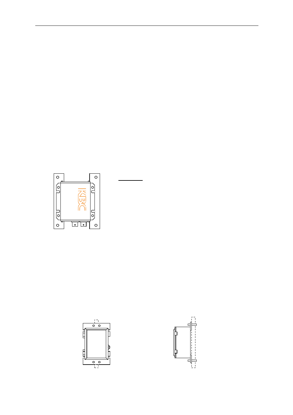
1. Attach KBC Encoder to mounting braces using self-thread Philips screws. Ensure
top and bottom holes are positioned at the outside corners and leave connection
loose to be able to screw into the housing. See Figure #1. Mount the Encoder
and brace assembly into the enclosure using four M5 x .9P x 10mm Philips pan
head screws. Tighten all eight screws. Attach the enclosure to a wall or pole (Pole
mounting hardware included).
2. Remove green connector from Encoder power supply in order to feed the cable
through the weatherproof plugs. Remove the black grommet from the white plug
and insert the power cable through the weatherproof plug. Reattach grommet
into plug and green connector onto power supply. Ensure white dashed cable is
inserted into 12V port and solid black cable into GRD port. If using a D900
Transceiver, place the transceiver on its side and adjust the antenna so it is
pointing up.
3. Attach an off-white painted bracket to the top and bottom of the enclosure. Use
four M5 x .9P x 10mm Philips pan head screws attaching the outer holes to the
four corner threaded ports on the backside of the enclosure. Mount enclosure to
pole or wall using two off-white painted brackets and hardware kit.
Figure #1
Encoder and brace
assembly
Side view of
mounted enclosure
Front view of
mounted enclosure
* LWE-ED Enclosure is included with EDKT-A and WESII-KT-ED system kits.