Quick start, Powering up, Pc connection – CUE ipCUE User Manual
Page 8: Using lan directly to pc
4. Quick Start
4.1.
Powering Up
Every ipCUE controller requires power from an external power supply. The standard CUEadapter /30W is
delivered with the unit. Attach the 2-pin connector of the power supply unit to the PWR IN connector located on
the rear panel of ipCUE controller and attach power cable to a power outlet. The LED labeled PWR will light up
when the unit is powered on.
4.2.
PC Connection
Using LAN Directly to PC
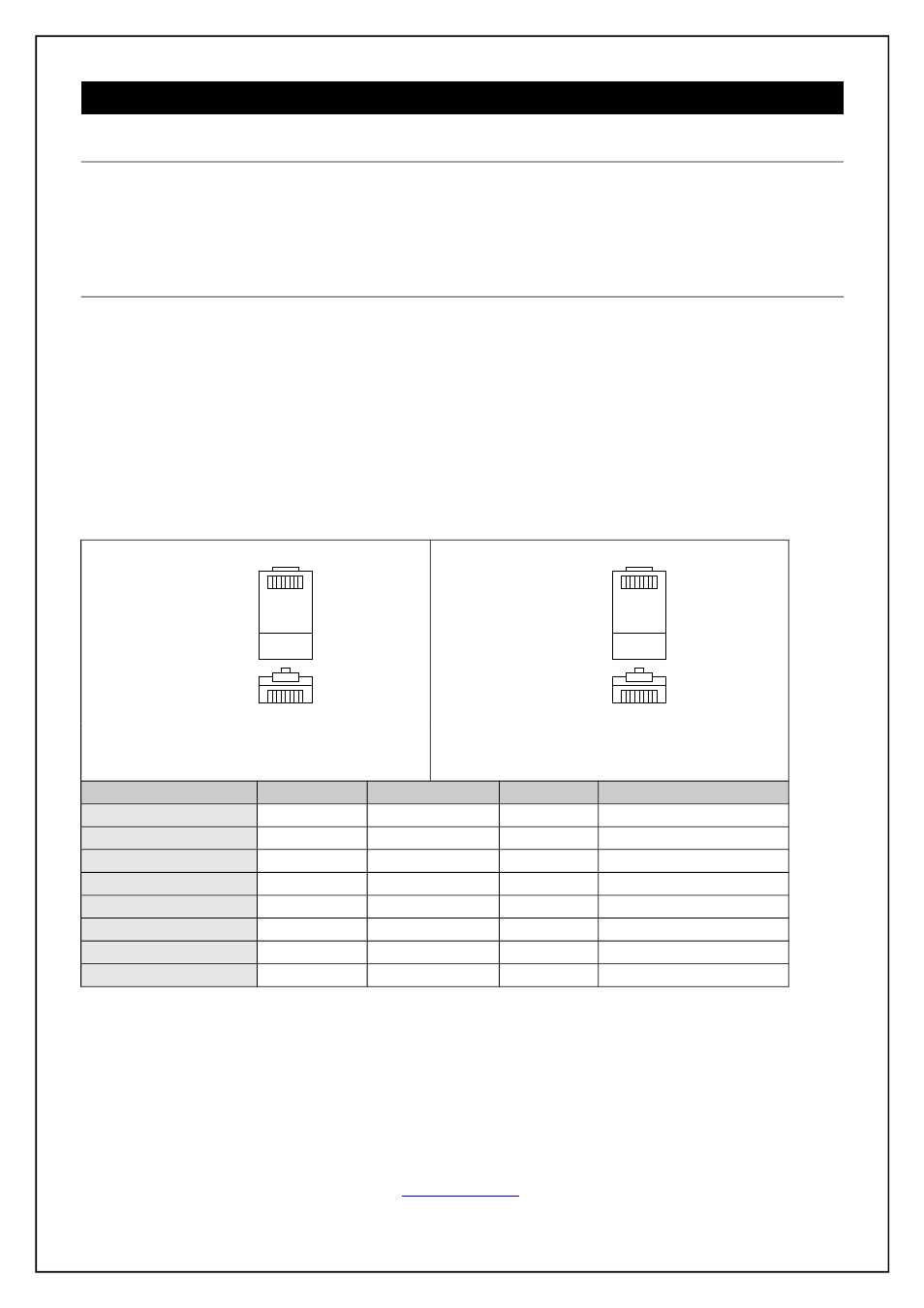
Attach one end of an RJ-45 Ethernet crossed-over cable to the ipCUE controller CUEnet (LAN) port and
attach the other end of the RJ-45 Ethernet cable to your computer.
Ethernet Crossed-Over Cable
This cable can be used to cascade hubs, or for connecting two Ethernet stations back-to-back without a hub. It
works with 10Base-T, 100Base-TX, 100Base-T4 and 1000Base-T. Use a good enough cable, if you are
confused about categories of cables then use Category 5 (enhanced) and you'll be fine even at 1000Base-T.
1
8
1
8
Top
Front
1
8
1
8
Top
Front
To Network Interface Card 1 (NIC 1)
Computer
RJ45 Male Connector
To Network Interface Card 2 (NIC 2)
Touch panel
RJ45 Male Connector
Name
NIC 1
Color
NIC 2
Name
TX+ (BI_DA+)
1
White/Orange
3
RX+ (BI_DB+)
TX- (BI_DA-)
2
Orange
6
RX- (BI_DB-)
RX+ (BI_DB+)
3
White/Green
1
TX+ (BI_DA+)
- (BI_DC+)
4
Blue
7
- (BI_DD+)
- (BI_DC-)
5
White/Blue
8
- (BI_DD-)
RX- (BI_DB-)
6
Green
2
TX- (BI_DA-)
- (BI_DD+)
7
White/Brown
4
- (BI_DC+)
- (BI_DD-)
8
Brown
5
- (BI_DC-)
That means that the White/Orange cable connected to NIC 1 pin 1 should go to NIC 2 pin 3 and NIC 1 pin 2 to
NIC 2 pin 6 etc.
User Manual ipCUE Controllers
Page 8 of 52