Cuewire device connection, Cuewire installation – CUE ipCUE User Manual
Page 30
8. CUEwire Device Connection
8.1.
CUEwire Installation
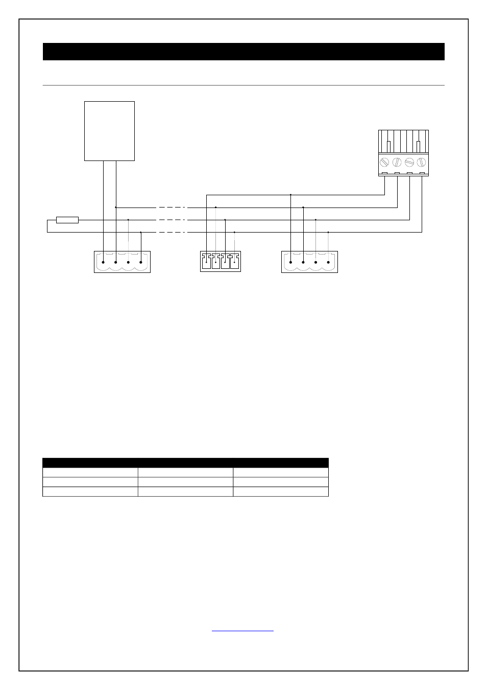
On the picture you can see a typical connection of CUEwire.
The cable consists of 4 wires. The first pair serves as a signal line. The second pair of wires serves for power
distribution. The signal conductors can have minimum 0.25 mm
2
, maximum capacity 100 pF/m.
The power distribution cable design depends on how many CUEwire devices are connected and on the
required length of the cable. The maximum voltage loss on the whole power distribution conductors should not
exceed 4 V on the ground wire and 4 V on the +24 V wire.
To supply power distribution line of the Bi-directional Serial RS-485 with Power 24 VDC (CUEwire) port on the
controller can be used. In this case the whole consumption should not exceed 2 A. In case of exceeding 2 A
consumption or for longer distances it is necessary to use external power supply +24 V for remote CUEwire
devices (see example of the Device N in the picture “Multiple CUEwire device connected to a CUEwire
Splitter” below).
Table of maximum cable lengths are
Consumption
Cable 1 mm
2
Cable 2 mm
2
10 W
200 m
400 m
20 W
100 m
200 m
30 W
60 m
130 m
User Manual ipCUE Controllers
Page 30 of 52
B-
A+
GND
+ 24 VDC
4-pin
4-pin
4-pin
CUEwire Device 1
External power
supply
+
2
4
V
D
C
G
N
D
Controller
CUEwire 4-pin Connector
(3.5 or 5 mm type)
120 ohm
CUEwire Device 2
CUEwire Device N