CUE ipCUE User Manual
Page 20
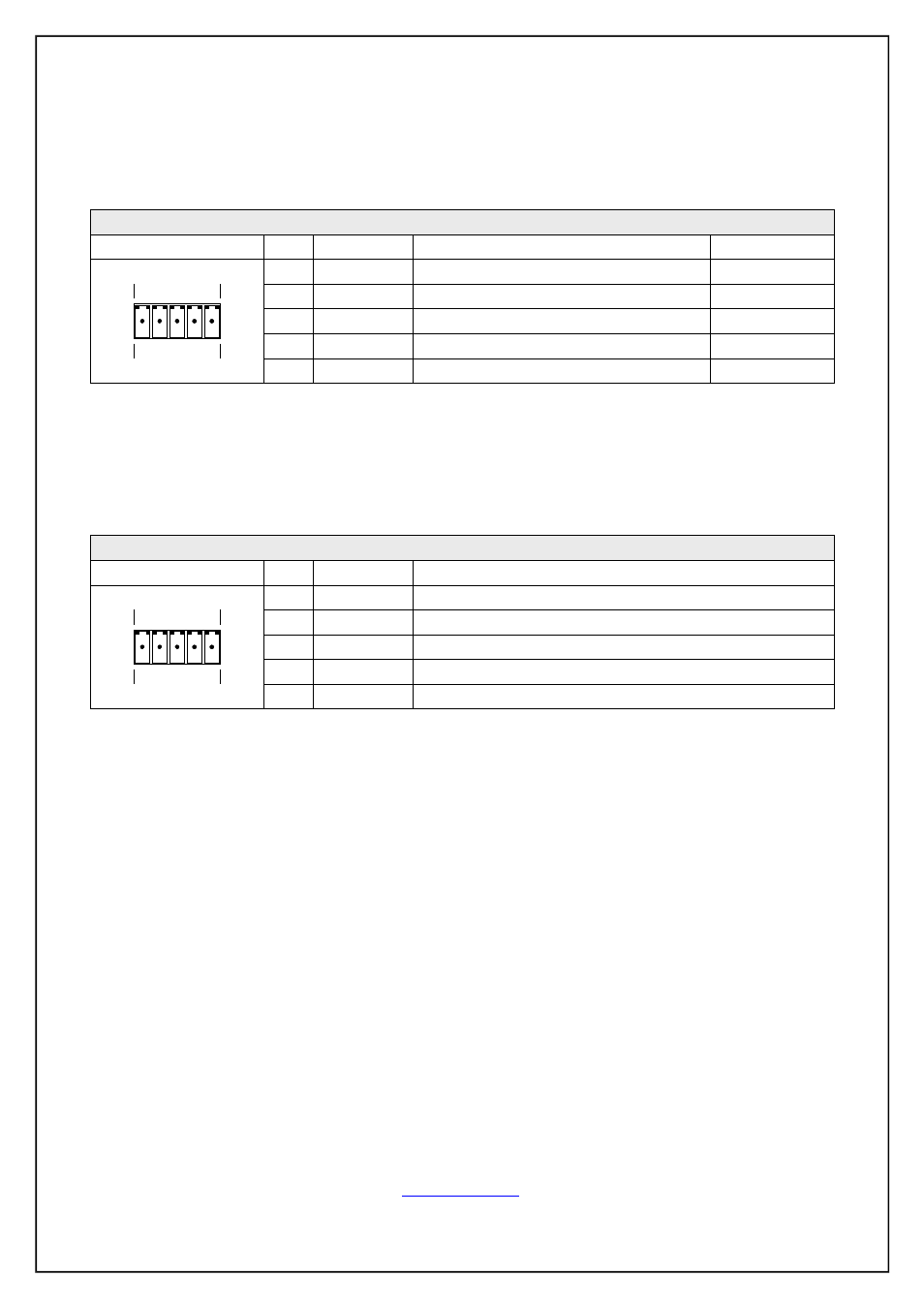
RS-422 Mode
This mode must be set in the programming application.
Connector pin out
RS-485 Mode
This mode must be set in the programming application.
Connector pin out
User Manual ipCUE Controllers
Page 20 of 52
Pin
1
2
3
4
5
Signal
Tx A+
Tx B-
GND
Rx A+
Rx B-
Description
RS-422 Transmit Data (Idles High)
Ground
RS-422 Transmit Data (Idles Low)
RS-422 Receive Data (Idles High)
RS-422 Receive Data (Idles Low)
From ipCUE
From ipCUE
To ipCUE
To ipCUE
Direction
5-pin 3.5 mm
RS-422
1 2 3 4 5
Pin
1
2
3
4
5
Signal
A+
B-
GND
N.C.
N.C.
Description
RS-485 Data +
Ground
RS-485 Data -
Not Connected
Not Connected
5-pin 3.5 mm
RS-485
1 2 3 4 5