Terminal panel features – Dukane 8808 User Manual
Page 18
8
1. Introduction
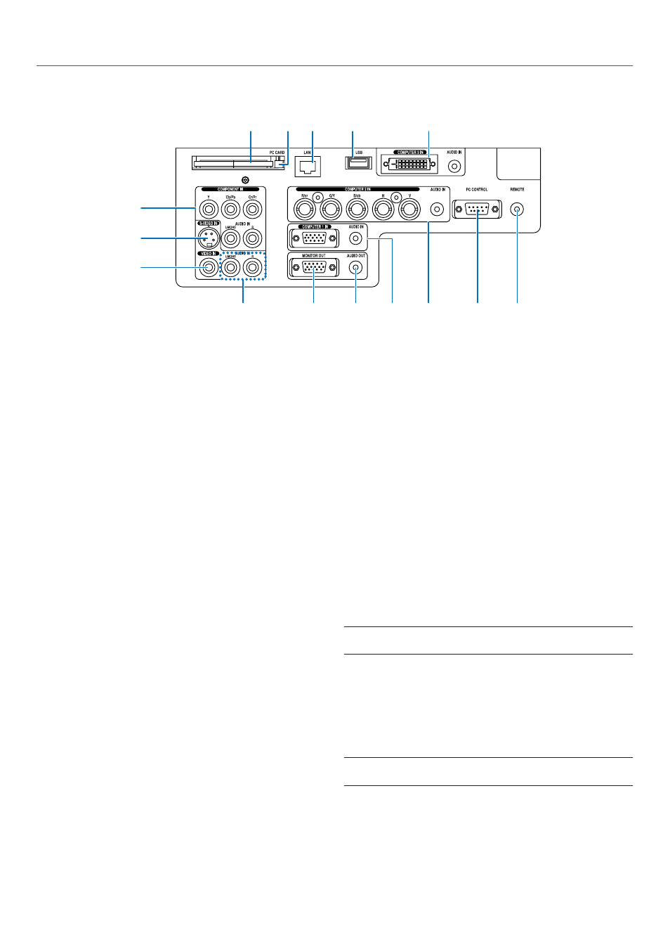
Terminal Panel Features
1. COMPUTER 1 IN/Component Connector (Mini D-
Sub 15 Pin) (→page
13
,
15
)
AUDIO IN (Stereo Mini Jack) (→page
13
,
14
,
16
)
2. COMPUTER 2 IN/Component (R/cr, G/V, B/cb, H,
V) Connectors (BNC x 5) (→page
13
)
AUDIO IN (Stereo Mini Jack) (→page
13
)
3. COMPUTER 3 IN Connector (DVI-D 24 Pin) (HDCP
compatible) (→page
14
)
AUDIO IN (Stereo Mini Jack) (→page
14
)
4. COMPONENT IN (Y, Cb/Pb, Cr/Pr) Connectors
(RCA) (→page
17
)
AUDIO L/MONO, R (RCA) (→page
17
)
5. S-VIDEO IN Connector (Mini DIN 4 Pin) (→page
18
)
6. VIDEO IN Connector (RCA) (→page
18
)
7. VIDEO/S-VIDEO AUDIO L/MONO, R (RCA) (→page
18
)
8. MONITOR OUT Connector (Mini D-Sub 15 Pin)
(→page
16
)
9. AUDIO OUT (Stereo Mini Jack) (→page
16
)
10. PC CONTROL Port (D-Sub 9 Pin) (→page
127
,
128
)
Use this port to connect your PC or control system to
control your projector via a serial cable. This enables
you to control the projector using serial communica-
tion protocol. A commercially available RS232C cross
cable is required to use this port. You can also control
the projector by using PC Control Utility 3.0 contained
on the supplied User Supportware 3 CD-ROM. To do
so you must first have PC Control Utility 3.0 installed
on your PC. If you are writing your own program, typi-
cal PC control codes are on page
127
.
11. Remote Jack (Stereo Mini Jack) (→page
11
)
NOTE: Connecting the remote cable to the REMOTE mini jack on
the terminal panel will make the wireless operation unavailable.
12. USB Port (Type A) (→page
38
,
59
)
13. LAN Port (RJ-45) (→page
19
,
89
)
14. PC CARD Eject Button (→page
22
)
15. PC CARD Slot (→page
21
)
NOTE: A dummy card is inserted into each slot at the time of
shipment. First remove the dummy cards before use.
The actual appearance of the terminal panel may differ slightly from that shown in the drawing, but this does not affect
the projector's performance.
4
5
6
7
8
9
1
2
10
11
15
14 13
12
3