BINDER KBF 115 User Manual
Page 92
KBF / KBF P (E5.3) 09/2014
page 92/110
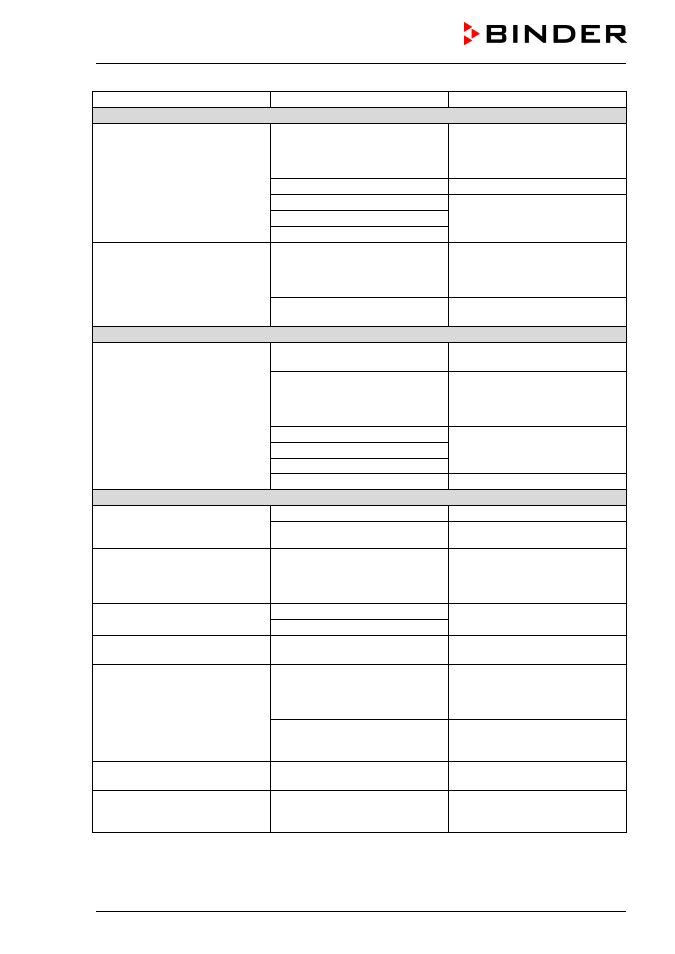
Fault description
Possible cause
Required measures
Heating (continued)
Mechanical safety device class
3.1 responds
(with option safety device class
3.3).
Limit temperature reached.
Check setting of temperature set-
point and of safety device class
3.1. If appropriate, select suitable
limit value.
Too much external heat load.
Reduce heat load.
Controller defective.
Contact BINDER service.
Safety device defective.
Semi-conductor relay defective
Mechanical safety device class
3.2 responds
(with option safety device class
3.3).
Limit temperature reached.
Check setting of temperature set-
point and of safety device class
3.2. If appropriate, select suitable
limit value.
Controller or safety device defec-
tive.
Contact BINDER service.
Refrigerating performance
Low or no refrigerating perfor-
mance.
Ambient temperature > 25 °C / 77
°F (chap.3.4).
Select cooler place of installation.
Combination of tempera-
ture/humidity values not in the
optimum range (see temperature
humidity diagram, Figure 21).
Select combination of tempera-
ture/humidity values in the opti-
mum range (chap. 12).
Compressor not turned on.
Contact BINDER service.
Electro-valves defective.
No or not enough refrigerant.
Too much external heat load.
Reduce heat load.
Humidity
Humidity fluctuation:
Control accuracy of ± 3 % r.H. is
not reached.
Door gasket defective.
Replace door gasket.
Door opened very frequently.
Open doors less frequently.
Humidity fluctuation, together
with temperature fluctuation
> 1 °C with a set-point approx.
3 °C above ambient temperature.
Place of installation too hot.
Select cooler place of installation
or contact BINDER service.
Low or no dehumidification.
Capillary tube blocked
Contact BINDER service.
Not enough refrigerant.
Icing at the evaporator plates.
Set-point was too long below
ambient temperature.
Defrost the unit (chap. 13).
Condensation at the walls of the
inner chamber.
Combination of tempera-
ture/humidity values not in the
optimum range (see temperature
humidity diagram, Figure 21)
Select combination of tempera-
ture/humidity values in the opti-
mum range (chap. 12).
Set-point was too long below
ambient temperature, icing in the
preheating chamber.
Defrost the unit (chap. 13)
Low humidity and temperature
accuracy.
Fan speed has been reduced.
Set fan speed to 100%.
Notification or alarm message
“HUMID SYSTEM” on the con-
troller.
Notification or error of the humidi-
ty system.
See chap. 11.2.