Encoder rs485, Encoder interface – Altera Multiaxis Motor Control Board User Manual
Page 20
Page 20
Functional Description
Multiaxis Motor Control Board
February 2014
Altera Corporation
Encoder RS485
For encoders that use an RS485 interface, configure the data pins for full-duplex
operation with combined TX and RX data or half-duplex operation with separate TX
and RX data. You may configure each channel independently.
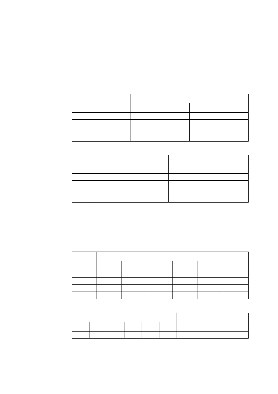
Table 11
lists the
jumpers to set for each channel.
Table 12
lists the jumper positions for encoder RS485s.
Out means fit no jumper; in means fit a jumper.
Encoder Interface
The Multiaxis Motor Control Board supports RS485, resolver, Hall effect and
quadrature encoders. You can configure each channel independently to support one
of these encoder standards at any one time.
Table 13
lists the jumpers to set for each
channel.
Table 14
lists the jumper positions for encoder interface selection.
Table 11. Jumpers for Each Channel for Encoder RS485 Data Configuration
Channel
Jumpers
A
B
0
J5, J6
J7, J8
1
J19, J20
J21, J22
2
J33, J34
J35, J36
3
J47, J48
J49, J50
Table 12. Encoder RS485 Data Configuration
Jumper Position
Data Configuration
Encoder
A
b
Out
Out
RX only.
—
Out
In
Bidirectional on RX pair.
EnDat
In
Out
Separate RX and TX.
—
In
In
Bidirectional on TX pair.
—
Table 13. Jumpers for Each Channel for Encoder Selection
Channel
Jumpers
A
B
C
D
E
F
0
J10
J11
J12
J13
J14
J15
1
J24
J25
J26
J27
J28
J29
2
J38
J39
J40
J41
J42
J43
3
J52
J53
J54
J55
J56
J57
Table 14. Encoder Interface Selection
Jumper Positions
Encoder Interface
A
B
C
D
E
F
In
In
In
Out
Out
Out
Resolver.