Altera PowerPlay Early Power Estimator User Manual
Page 22
3–6
UG-FPGAPWRCAL-2.0
Altera Corporation
PowerPlay Early Power Estimator User Guide: Stratix, Stratix GX & Cyclone FPGAs
October 2005
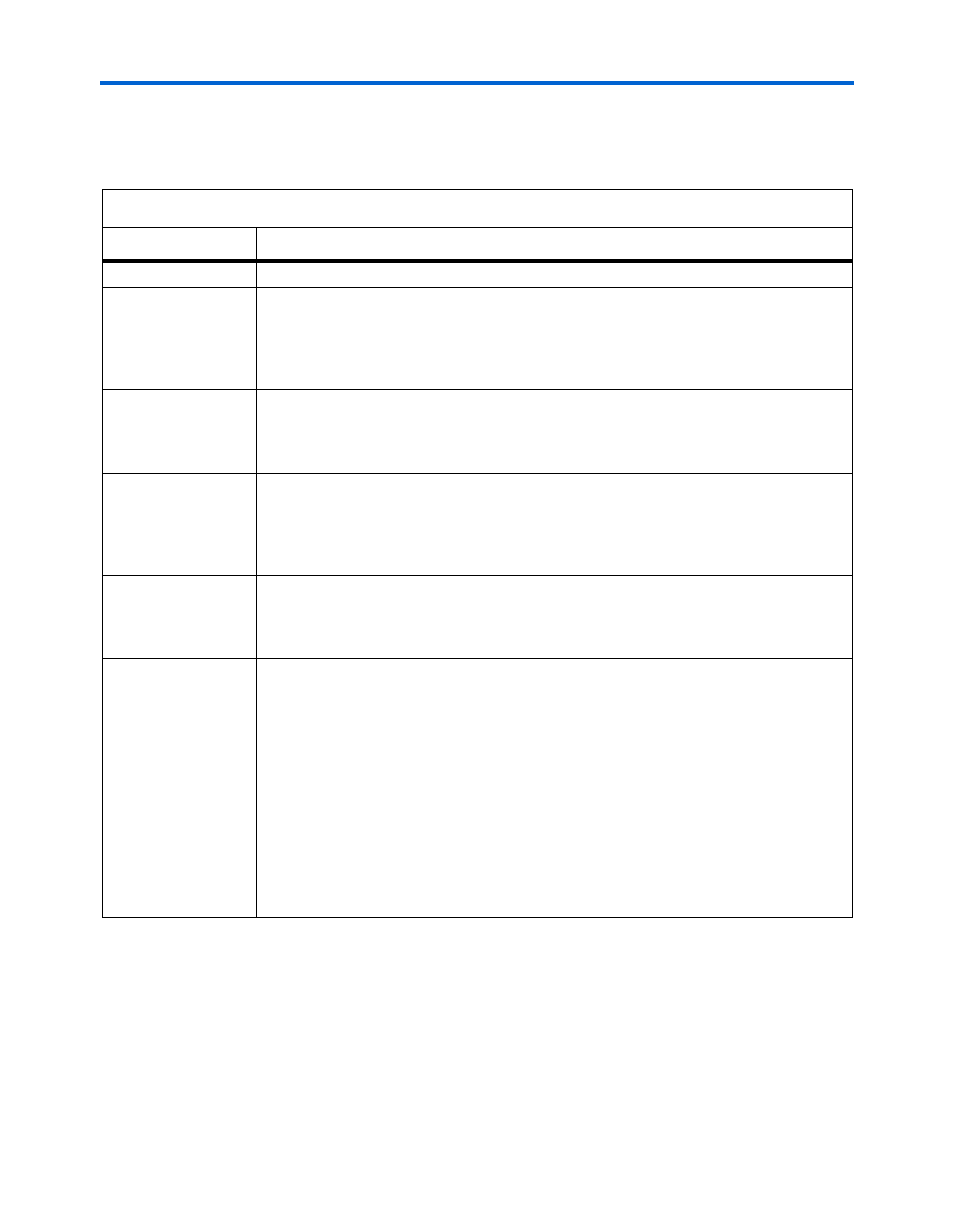
PowerPlay Early Power Estimator Input Values
describes the values that are entered in the LEs section of the
PowerPlay early power estimator.
Table 3–2. Logic Elements (LEs) Section Information
Column Heading
Description
Design Module
Enter a name for the design module in this column. This is an optional value.
f
M A X
(MHz)
This is the frequency of the clock feeding the LEs. This value is limited by the maximum
frequency specification for the device family. If you have asynchronous logic that is not
fed by a clock or is combinational logic, you should consider this as a design module.
Estimate how often this logic toggles based on your design. Using this information, enter
an appropriate clock frequency and toggle percentage.
Average Fan-Out
The average fan-out per LE of your design. The Quartus II reports this information in the
Average Fan-Out row in the Fitter > Resource Section > Fitter Resource Usage
Summary section of the Compilation Report. The average fan-out usually ranges from 1
to 5 with a design average of 3.4.
# LEs
The number of LEs used in the whole design is reported in the Quartus II software in the
Logic Cells row in the Fitter > Resource Section > Fitter Resource Usage Summary
section of the Compilation Report. The number of LEs used in each design entity is found
in the Fitter Resource Utilization by Entity section of the Compilation Report or the
Hierarchies tab of the Project Navigator.
# LEs w/carry
The number of LEs in the design module that use carry chains. The Quartus II software
reports the number of LEs using carry chains in the Logic Cells in Carry Chains row in
the under Fitter > Resource Section > Fitter Resource Usage Summary section of the
Compilation Report.
Toggle %
The average percentage of LEs toggling on each clock cycle. The toggle percentage
ranges from 0 to 100%. Typically, the toggle percentage is 12.5%, which is the toggle
percentage of a 16-bit counter. To be more conservative, you can use a higher toggle
percentage.
For instance, a TFF with its input tied to V
C C
has a toggle rate of 100% because its output
is changing logic states on every clock cycle.
for an example.
shows an example of a 4-bit counter. The first TFF with least significant bit (LSB) output
cout0
has a toggle rate of 100% because
cout0
toggles on every clock cycle. The
toggle rate for the second TFF with output
cout1
is 50% since
cout1
only toggles on
every two clock cycles. Consequently, the toggle rate for the third TFF with output
cout2
and fourth TFF with output
cout3
are 25% and 12.5%, respectively. Therefore, the
average toggle percentage for this 4-bit counter is (100 + 50 + 25 + 12.5)/4 = 46.875%.
(1)
This value is limited by the largest number of LEs available in the largest device in the family. You must verify that
the number of LEs entered does not exceed the number of LEs available in your target device
.