Using a heat sink, Using a heat sink –21 – Altera PowerPlay Early Power Estimator User Manual
Page 33
Chapter 3: Using Cyclone III PowerPlay Early Power Estimator
3–21
Power Analysis
© June 2009 Altera Corporation
PowerPlay Early Power Estimator User Guide for Cyclone III FPGAs
The total power is calculated based on the
JA
, ambient temperature, and junction
temperature using the following
.
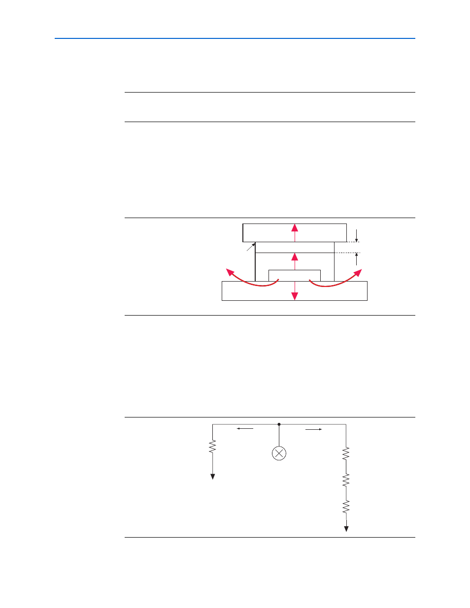
Using a Heat Sink
When a heat sink is used, the major paths of power dissipation are from the device
through the case, thermal interface material, and heat sink. There is also a path of
power dissipation through the board. The path through the board has much less
impact than the path to air.
Figure 3–16
shows the thermal representation with a heat sink.
In the model used in the PowerPlay Early Power Estimator, power can be dissipated
through the board or through the case and heat sink. The thermal resistance of the
path through the board is referred to as the junction-to-ambient bottom thermal
resistance (
JA BOTTOM
). The thermal resistance of the path through the case, thermal
interface material, and heat sink is referred to as the junction-to-ambient thermal
resistance (
JA TOP
).
Figure 3–17
shows the thermal model for the PowerPlay Early Power Estimator.
Equation 3–2. Total Power Calculation for Not Using a Heat Sink
Figure 3–16. Thermal Representation with a Heat Sink
Figure 3–17. Thermal Model for the PowerPlay Early Power Estimator with a Heat Sink
P
TJ TA
–
JA
-----------------------
=
Heat Sink
Case
Device
Board
Thermal Interface Material
θ
JA BOTTOM
θ
JC
θ
SA
Thermal Representation with Heat Sink
θ
CS
θ
JC
θ
CS
θ
SA
θ
JA BOTTOM
T
J
T
A
T
J
T
C
T
S
T
A
Power (P)
Power (P)
Heat Source