Dsp –9 – Altera PowerPlay Early Power Estimator User Manual
Page 21
Chapter 3: Using Cyclone III PowerPlay Early Power Estimator
3–9
PowerPlay Early Power Estimator Inputs
© June 2009 Altera Corporation
PowerPlay Early Power Estimator User Guide for Cyclone III FPGAs
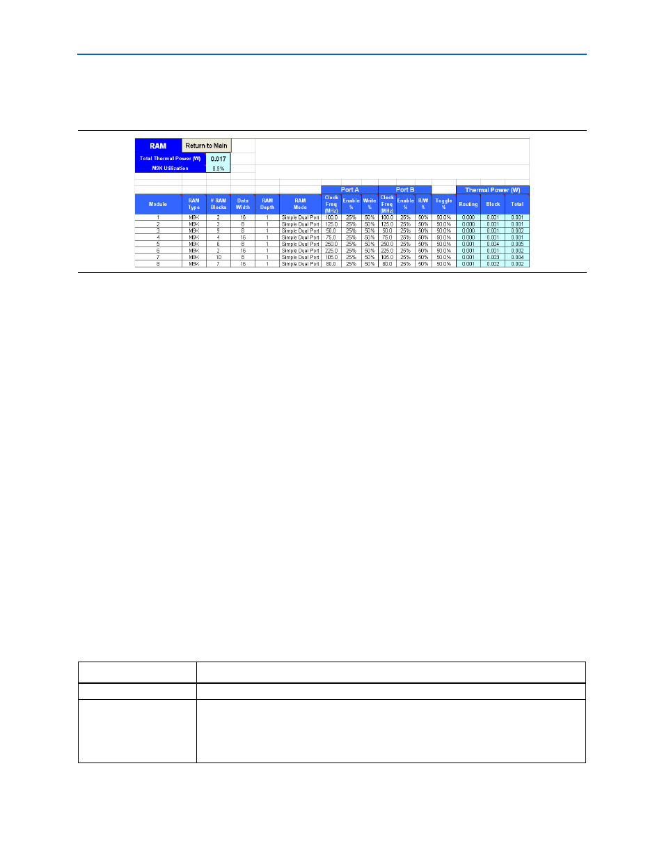
Figure 3–5
shows the RAM section of the PowerPlay Early Power Estimator and the
estimated power consumed by RAM blocks.
DSP
Cyclone III device family implement DSP functions in embedded multipliers. These
embedded multiplier blocks are optimized for multiplier-intensive, low-cost DSP
applications. The DSP section in the PowerPlay Early Power Estimator provides
power information for Cyclone III multiplier blocks.
Each row in the DSP section represents a multiplier design module where all
instances of the module have the same configuration, clock frequency, toggle
percentage, and register usage. If some or all DSP or multiplier instances have
different configurations, you must enter the information in different rows. You must
enter the following information for each multiplier module:
■
Configuration
■
Number of instances
■
Clock frequency (f
MAX
) in MHz
■
Toggle percentage of the data outputs
■
Whether or not the inputs and outputs are registered
f
For more information about Cyclone III DSP block configurations, refer to the
apter in volume 1 of the Cyclone III Device
Handbook.
Table 3–4
describes the values that must be entered in the DSP section of the
PowerPlay Early Power Estimator.
Figure 3–5. RAM Section in the PowerPlay Early Power Estimator
Table 3–4. DSP and Multiplier Section Information (Part 1 of 2)
Parameters
Description
Module
Enter a name for the DSP module in this column. This is an optional value.
Configuration
Select the DSP block configuration for the module. Cyclone III DSP blocks offer the following
configurations:
■
9 × 9 multiplier
■
18 × 18 multiplier