Altera PowerPlay Early Power Estimator User Manual
Page 29
Chapter 3: Using Cyclone III PowerPlay Early Power Estimator
3–17
PowerPlay Early Power Estimator Inputs
© June 2009 Altera Corporation
PowerPlay Early Power Estimator User Guide for Cyclone III FPGAs
Table 3–8
describes the parameters in the Clock section of the PowerPlay Early Power
Estimator.
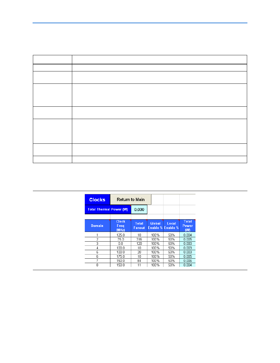
Figure 3–11
shows the Clocks section of the PowerPlay Early Power Estimator and
the estimated power consumed by clocks.
Table 3–8. Clock Section Information
Parameter
Description
Domain
Enter a name for the clock network in this column. This is an optional value.
Clock Freq (MHz)
Enter the frequency of the clock domain. This value is limited by the maximum frequency
specification for the device family.
Total Fanout
Enter the total number of flip-flops and RAM, DSP, and I/O blocks fed by this clock. The number of
resources driven by every global clock signal is reported in the Fan-out column of the Quartus II
Compilation Report. In the Compilation Report, select Fitter and click Resource Section. Select
Global & Other Fast Signals and click Fan-out.
Global Enable %
Enter the average % of time that the entire clock tree is enabled. Each global clock buffer has an
enable signal that can be used to dynamically shut down the entire clock tree.
Local Enable %
Enter the average % of time that clock enable is high for destination flip-flops.
Local clock enables for flip-flops in LEs are promoted to LAB-wide signals. When a given flip-flop is
disabled, the LAB-wide clock is also disabled, cutting clock power in addition to power for
down-stream logic. This sheet models only the impact on clock tree power.
Total Power
This is the total power dissipation due to clock distribution (in W). This value is calculated
automatically.
User Comments
Enter any comments. This is an optional entry.
Figure 3–11. Clocks Section in the PowerPlay Early Power Estimator