Thermal analysis, Thermal analysis –19 – Altera PowerPlay Early Power Estimator User Manual
Page 31
Chapter 3: Using Cyclone III PowerPlay Early Power Estimator
3–19
Power Analysis
© June 2009 Altera Corporation
PowerPlay Early Power Estimator User Guide for Cyclone III FPGAs
Table 3–9
describes the thermal power parameters in the PowerPlay Early Power
Estimator.
Thermal Analysis
You can choose to enter T
J
directly or compute T
J
based on information provided. If
you choose to enter T
J
, select User Entered T
J
in the Input Parameters section. If you
choose to automatically compute T
J
, select Auto Computed T
J
in the Input
Parameters
section.
When computing T
J
value obtained, the ambient temperature of the device, airflow,
heat sink solution, and board thermal model are considered to determine the junction
temperature (T
J
) in °. T
J
is the estimated operating junction temperature based on your
device and thermal conditions.
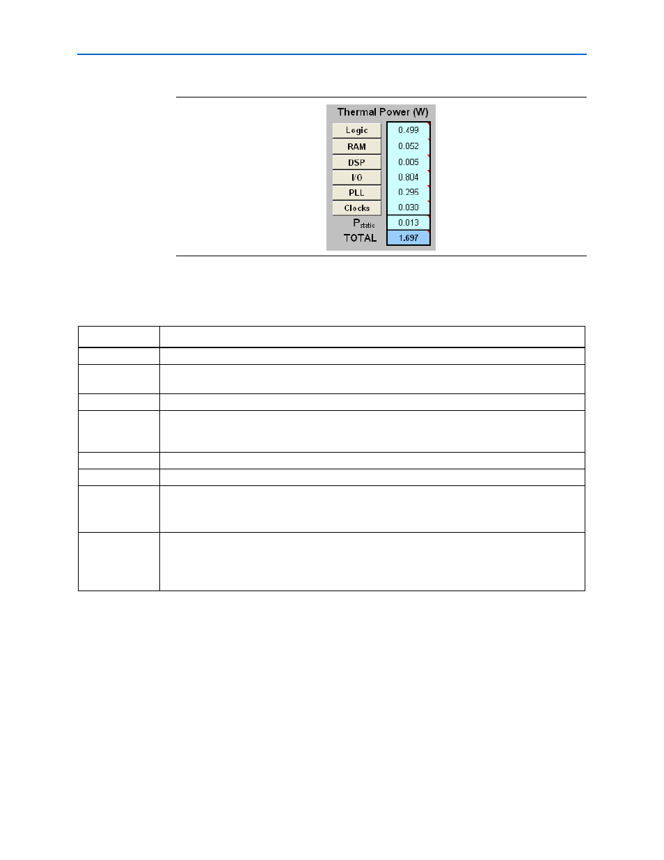
Figure 3–13. Thermal Power in the PowerPlay Early Power Estimator
Table 3–9. Thermal Power Section Information
Parameter
Description
Logic
This shows the dynamic power consumed by LUTs and associated routing. For details, click Logic.
RAM
This shows the dynamic power consumed by RAM blocks and associated routing. For details, click
RAM.
DSP
This shows the dynamic power consumed by DSP blocks and associated routing. For details, click DSP.
I/O
This shows the thermal power consumed by I/O pins and associated routing. This includes static power
dissipated in terminated I/O standards on-chip and stand-by power dissipated in I/O banks. For details,
click I/O.
PLL
This shows the dynamic power consumed by PLLs. For details, click PLL.
Clocks
This shows the dynamic power consumed by clock networks. For details, click Clocks.
P
static
This shows the static power consumed regardless of clock frequency. This does not include static I/O
current due to termination resistors, which is included in the I/O power above.
P
static
is affected by junction temperature, selected device, and power characteristics.
TOTAL
This shows the total power dissipated as heat from the FPGA. This does not include power dissipated in
off-chip termination resistors.
For current draw from the FPGA supply rails, refer to
“Power Supply Current (A)” on page 3–23
. This
may differ due to currents supplied to off-chip components and thus not dissipated as heat in the FPGA.