Airflow, Airflow –14 – Altera PowerPlay Early Power Estimator for Altera CPLDs User Manual
Page 24
2–14
Chapter 2: PowerPlay Early Power Estimator Worksheets
Factors Affecting the PowerPlay Early Power Estimator Spreadsheet Accuracy
PowerPlay Early Power Estimator for Altera CPLDs User Guide
December 2010
Altera Corporation
The Quartus II software can determine toggle rates of each resource used in the
design if you provide information from simulation tools. Designs can be simulated in
many different tools and the information provided to the Quartus II software through
a Signal Activity File (.saf). The Quartus II PowerPlay Power Analyzer provides the
most accurate power estimate. You can import the Comma-Separated Value File (.csv)
from the Quartus II software into the PowerPlay EPE spreadsheet for estimating
power after the design is complete.
Airflow
The PowerPlay EPE spreadsheet allows you to specify the airflow present at the
device. This value affects thermal analysis and can significantly affect the power
consumed by the device. To obtain an accurate estimate, you must correctly determine
the airflow at the CPLD, not the output of the fan providing the airflow.
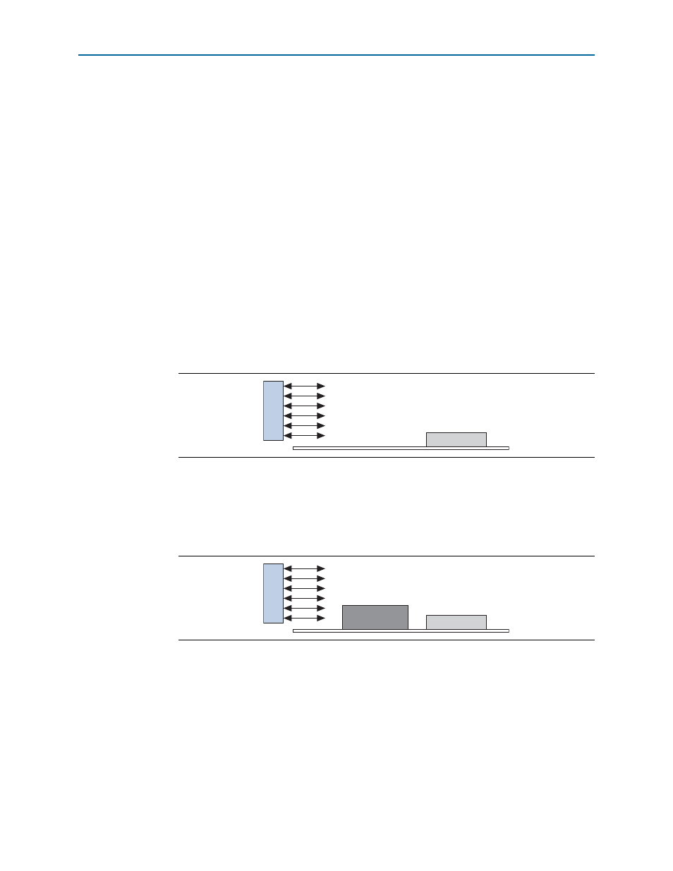
It is often difficult to place the device adjacent to the fan providing the airflow. The
path of the airflow is likely to traverse a length on the board before reaching the
device, thus diminishing the actual airflow the device receives.
Figure 2–13
shows a
fan that is placed at the end of the board. The airflow at the CPLD is weaker than it is
at the fan.
It is also necessary to take into consideration the blocked airflow.
Figure 2–14
shows a
device blocking the airflow from the CPLD, significantly reducing the airflow seen at
the CPLD. The airflow from the fan also has to cool board components and other
devices before reaching the CPLD.
The considerations above can heavily influence the airflow received at the device.
When entering information into the PowerPlay EPE spreadsheet, you have to
consider these implications in order to get an accurate airflow value at the CPLD.
Figure 2–13. Airflow and CPLD Position
Figure 2–14. Airflow with Component and CPLD Positions
F
A
N
CPLD
F
A
N
CPLD
Device