Power, Power –3 – Altera PowerPlay Early Power Estimator for Altera CPLDs User Manual
Page 13
Chapter 2: PowerPlay Early Power Estimator Worksheets
2–3
Power Estimation Using the PowerPlay Early Power Estimator
December 2010
Altera Corporation
PowerPlay Early Power Estimator for Altera CPLDs User Guide
Power
This section describes the power dissipated in the MAX II and MAX V devices. The
total thermal power is shown in mWatts and is a sum of the thermal power of all the
resources being used in the device.
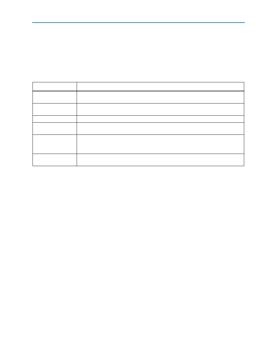
lists the thermal power parameters in the PowerPlay EPE spreadsheet, as
Table 2–2. Power Section Information
Column Heading
Description
Clocks
Represents the dynamic power consumed by the clock networks. To view the details, click
Clocks.
Logic
Represents the dynamic power consumed by the logic elements (LEs) and associated routing. To
view the details, click Logic.
UFM
Represents the dynamic power consumed by the UFM block. To view the details, click UFM.
I/O
Represents the dynamic power consumed by the I/O pins and associated routing. To view the
details, click I/O.
P
STANDBY
Represents the static power consumed irrespective of the clock frequency. The value includes
static power consumed by the I/O banks and the voltage regulator.
P
STANDBY
depends on the device you select and the V
CCINT
supply voltage.
P
TOTAL
Represents the total power consumed by the CPLD device. For more information about the
current draw from the CPLD supply rails, refer to
“Power Supply Current” on page 2–5
.