Altera NCO MegaCore Function User Manual
Page 29
After the clock enable is asserted, the oscillator outputs sinusoidal samples at a rate of one sample per N
clock cycles, where N is the magnitude precision. The IP core has an initial latency of L clock cycles; the
exact value of L depends on the parameters that you set.
Table 3-7: Latency Values for Different Architectures
Architecture
Variation
Latency
(1)
,
(2)
Base
Minimum
Maximum
Small ROM all
7
7
13
Large ROM all
4
4
10
Multiplier-
Based
Throughput = 1, Logic cells
11
11
17
Multiplier-
Based
Throughput = 1, Dedicated, Special case
(3)
8
8
14
Multiplier-
Based
Throughput = 1, Dedicated, Not special
case
10
10
16
Multiplier-
Based
Throughput = 1/2
15
15
26
CORDIC
Parallel
2N + 4
20
(4)
74
(5)
CORDIC
Serial CORDIC
2N + 2
18
(6)
258
(7)
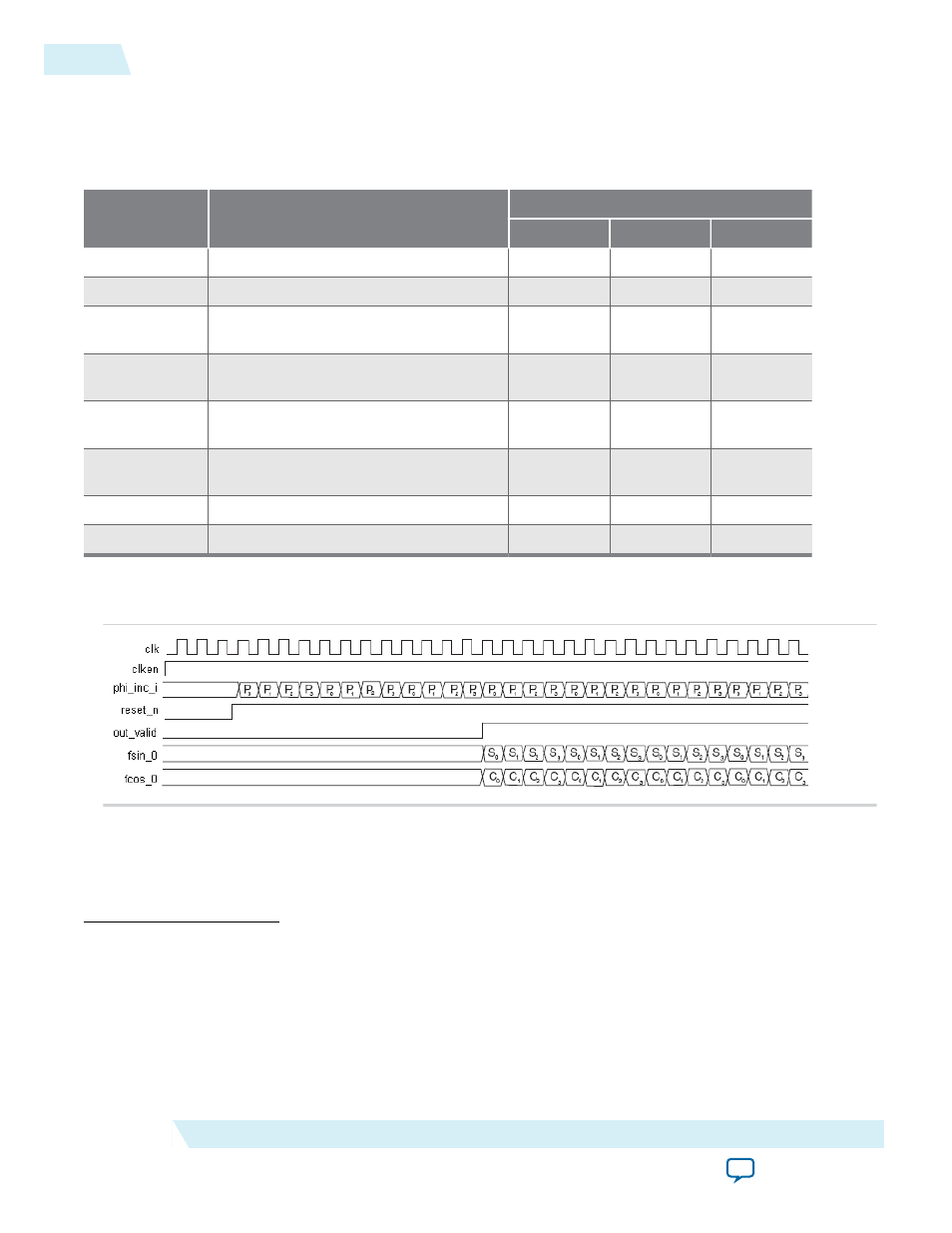
Figure 3-8: Multi-Channel NCO Timing Diagram with M = 4.
The IP core sequentially interleaves and loads input phase increments for each channel, P
k
The phase increment for channel 0 is the first value read in on the rising edge of the clock following the
de-assertion of reset_n (assuming clken is asserted) followed by the phase increments for the next (M-1)
channels. The output signal
out_valid
is asserted when the first valid sine and cosine outputs for channel
0, S
0
, C
0
, respectively are available.
(1)
Latency = base latency + dither latency+ frequency modulation pipeline + phase modulation pipeline (×N
for serial CORDIC).
(2)
Dither latency = 0 (dither disabled) or 2 (dither enabled).
(3)
Special case: (9 <= N <= 18 && WANT_SIN_AND_COS).
(4)
Minimum latency assumes N = 8.
(5)
Maximum latency assumes N = 32
(6)
Minimum latency assumes N = 8.
(7)
Maximum latency assumes N = 32
3-12
NCO IP Core Timing Diagrams
UG-NCO
2014.12.15
Altera Corporation
NCO IP Core Functional Description