Altoct megafunction ports, Input ports, Altoct megafunction ports –8 – Altera Dynamic Calibrated On-Chip Termination User Manual
Page 15: Input ports –8
3–8
Chapter 3: Functional Description
ALTOCT Megafunction Ports
Dynamic Calibrated On-Chip Termination (ALTOCT) Megafunction
February 2012
Altera Corporation
User Guide
In the simulation waveform shown in
, all of the calibration blocks have
their
calibration_request
signals asserted at a particular time. Initially, requests for
calibration are done simultaneously for calibration block[0] and
calibration_request[3]
. This can be observed in the behavior of the
calibration_request[3]
and
calibration_request[0]
signals. Both signals are
asserted and deasserted at the same time.
Observe the behavior of the
calibration_busy[3]
and
calibration_busy[0]
signals.
Notice that both are also asserted and deasserted at the same time. This is because
multiple OCT calibration blocks can be calibrated at the same time. When these
signals get deasserted, calibration is complete.
Next, observe the
cal_shift_busy[3]
and
cal_shift_busy[0]
signals. They are both
asserted at the same time as the
calibration_busy[3]
and
calibration_busy[0]
signals, and both signals get deasserted after a number of clock cycles. These signals
indicate the status of calibration and serial shifting of the termination codes.
Notice that the
cal_shift_busy[3]
and
cal_shift_busy[0]
signals get deasserted at
different time—
cal_shift_busy[0]
gets deasserted first and followed by
cal_shift_busy[3]
. This is because the shifting process is serial, and only one
calibration block can be active at a time. In the event of multiple calibration block
requests, the priority calibration block[x] is based on this order. x=0, 1, 2, 3, 4, 5, 6, 7, 8,
9, which means calibration block[0] shift codes first and then followed by the other
blocks in the order. Observe
, the
cal_shift_busy[0]
gets deasserted first
and then followed by
cal_shift_busy[3]
. This is because calibration block[0] has
higher priority than calibration block[3].
Finally, the calibrated codes must be converted from serial format to parallel format
before being used in the I/O buffers. This is done by asserting and deasserting the
s2pload[0]
and
s2pload[3]
signals for 1 clock cycle only after
cal_shift_busy[3]
and
cal_shift_busy[0]
signals have been deasserted. See
.
Similar calibration process as described on
applies to the remaining portion of the
waveform. However, it applies to calibration block[2] and calibration block[1].
ALTOCT Megafunction Ports
lists the input and output ports for the ALTOCT
megafunction.
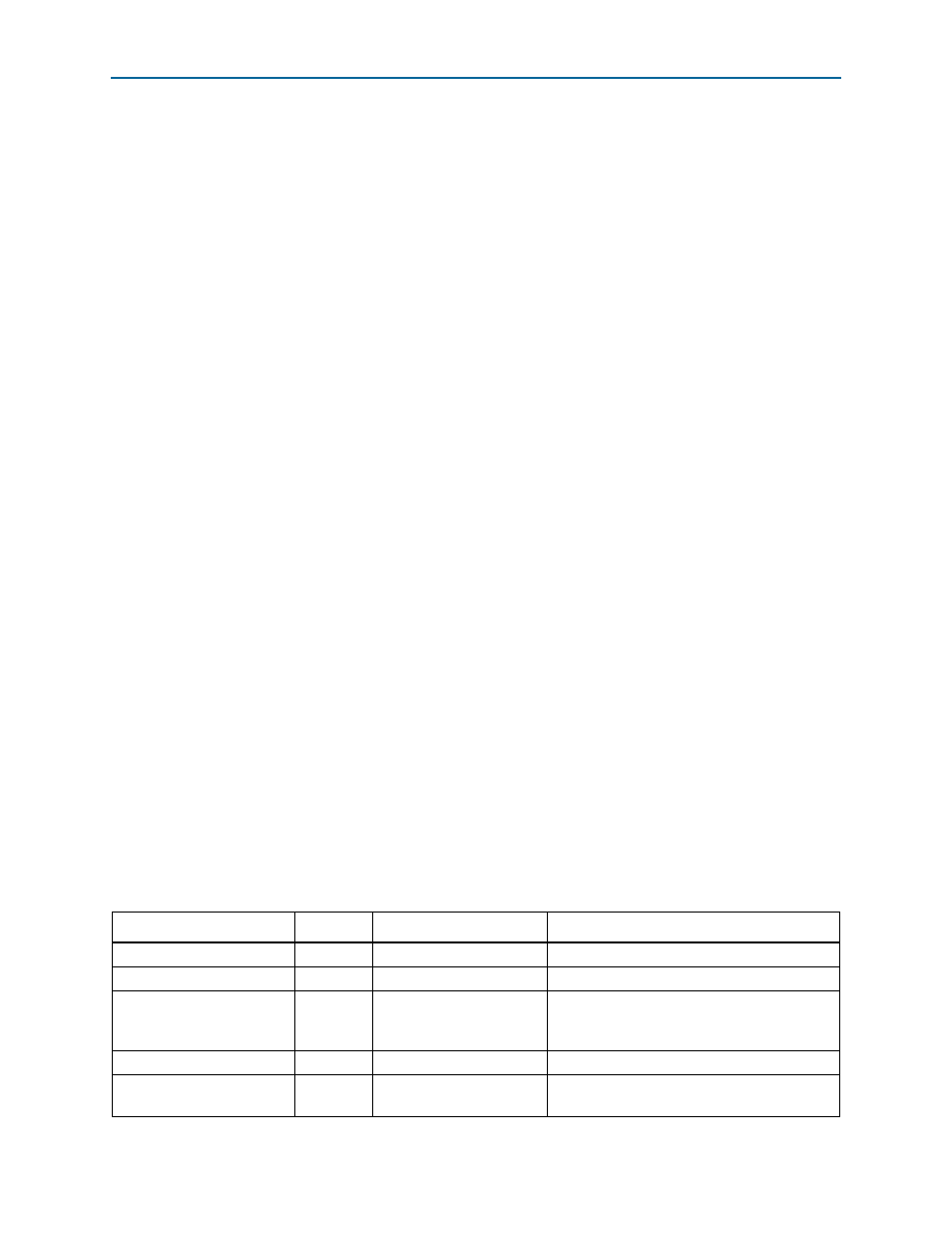
Input Ports
Table 3–2. ALTOCT Megafunction Input Ports
Port Name
Required
Description
Comments
aclr
No
Asynchronous clear
If omitted, value is GND
calibration_request
Yes
User request for calibration
Input port
[OCT_BLOCK_NUMBER - 1..0]
wide
calibration_wait
No
Clock cycles to wait before
starting calibration after
calibration request
Input port
[OCT_BLOCK_NUMBER - 1..0]
wide. If omitted, value is GND
clock
Yes
System clock
–—
rdn
Yes
Pull-down reference
resistor
Input port
[OCT_BLOCK_NUMBER - 1..0]
wide