Altera Dynamic Calibrated On-Chip Termination User Manual
Page 14
Chapter 3: Functional Description
3–7
Functional Simulation in the ModelSim-Altera Software
February 2012
Altera Corporation
Dynamic Calibrated On-Chip Termination (ALTOCT) Megafunction
User Guide
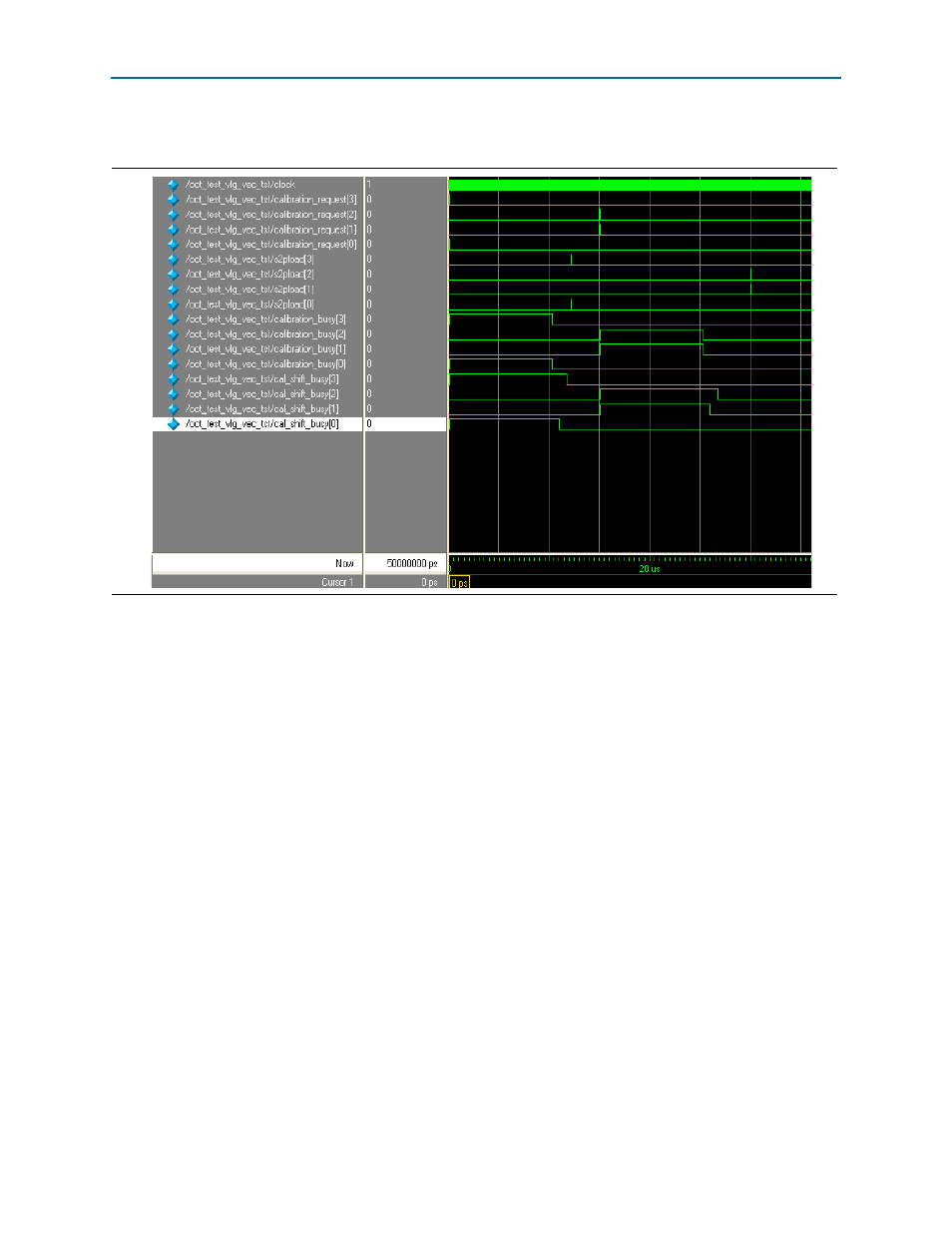
shows the expected simulation results in the ModelSim-Altera software.
For these functional results, the primary objective is to highlight the dynamic
calibration process. The design example uses four calibration blocks named
calibration block [x], with x=0, 1, 2, 3.
Each calibration block has its own set of control and data signals. For example,
calibration block[3]
has
calibration_request[3]
,
calibration_busy[3]
, and
cal_shift_busy[3]
signals.
To request calibration on
calibration block[x]
, the
calibration_request[x]
signal
must be asserted for at least 1 clock cycle to initiate the calibration. Multiple
calibration block requests are allowed.
The
calibration_busy[x]
signal indicates the calibration process that is being
performed in
calibration block[x]
. Calibration typically takes 200 clock cycles.
Calibration is complete when the
calibration_busy[x]
signal is deasserted.
The
cal_shift_busy[x]
signal is asserted at the same time as the
calibration_busy[x]
signal. This signal actually indicates both the duration of the
calibration and the serial shifting of termination codes from
calibration block[x]
to
the particular I/O buffers. Serial shifting of series termination codes typically takes 14
clock cycles.
After calibrated codes are shifted in serially to the particular I/O bank, the calibrated
codes must be converted from serial format to parallel format before being used in the
I/O buffers. To perform the conversion, the
s2pload[x]
signal is asserted at any time
for 1 clock cycle after the shifting process.
Figure 3–3. ModelSim-Altera Simulation Waveforms