Altera Dynamic Calibrated On-Chip Termination User Manual
Page 11
3–4
Chapter 3: Functional Description
Design Example: Series Calibration for Four Calibration Blocks Using Stratix III Device
Dynamic Calibrated On-Chip Termination (ALTOCT) Megafunction
February 2012
Altera Corporation
User Guide
8. In the MegaWizard Plug-In Manager pages, select or verify the configuration
settings shown in
. Click Next to advance from one page to the next.
9. Click Finish. The
cal_out
module is now built.
10. In the Symbol window, click OK.
11. Move the mouse to align the cal_out symbol with the existing ports in the
altoct_ex.bdf
file. Click to place the symbol. You have now completed the design
file.
12. On the File menu, click Save.
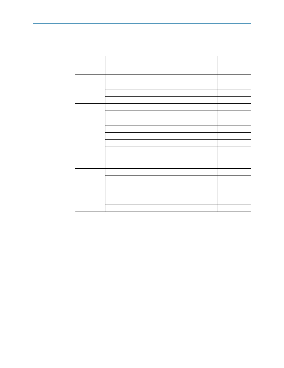
Table 3–1. Configuration Settings for ALTOCT Design Example
MegaWizard
Plug-in
Manager Page
Configuration Setting
Value
2a
Select a megafunction
ALTOCT
Which device family will you be using?
Stratix III
Which type of output file do you want to create?
Verilog HDL
What name do you want for the output file?
cal_out
3
Currently selected device family
Stratix III
Match project/default
Turned on
Calibrate OCT on power-up
Turned off
How many OCT blocks should be used?
4
Enable parallel termination
Turned off
Create ‘calibration_wait’ input port to prevent calibration
Turned off
Create ‘clken’ input port
Turned off
Enable independent calibration/shift
Turned off
4
Generate netlist
Turned off
5
Variation file
Turned on
Quartus II symbol file
Turned on
Instantiation template file
Turned on
Verilog HDL black-box file
Turned on
AHDL Include file
Turned on
VHDL component declaration file
Turned on