Interface signals, Pad interface signals – Altera GPIO User Manual
Page 9
The following table lists the Altera GPIO IP core main interfaces:
Table 2: Altera GPIO IP Core Interfaces
Interface
Description
Pad Interface
Connects the Altera GPIO IP core to the pads. This interface can be an input,
output or bidirectional interface, depending on the configuration of the
Altera GPIO IP core.
Data Interface
An input and/or output interface to the core. Consists of different signals,
depending on the configuration of the Altera GPIO IP core.
Clock Interface
An input clock interface. Consists of different signals, depending on the
configuration of the Altera GPIO IP core. The Altera GPIO IP core can have
0, 1, 2 or 4 clock inputs depending on the configuration. Clock ports appear
differently in different configurations, to reflect the actual function
performed by the clock signal.
Termination Interface
Connects the Altera GPIO IP core to the buffers.
Reset Interface
Connects the Altera GPIO IP core to the DDIOs.
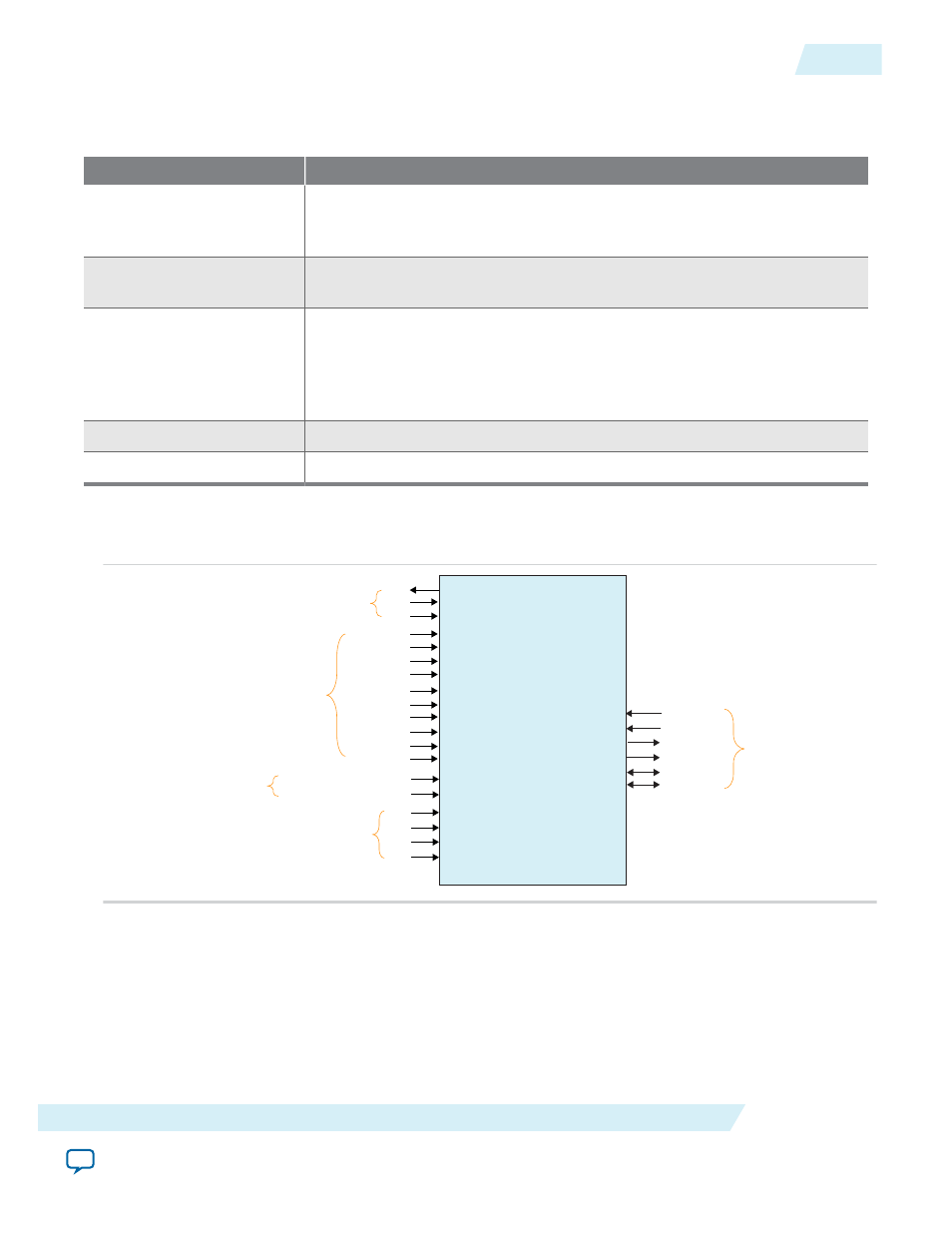
Interface Signals
The following figure list the signals for the data, clock, termination, reset, and pad interfaces.
din
pad_out
pad_in
oe
pad_io
pad_io_b
pad_out_b
ck
sclr
aclr
aset
sset
ck_fr
ck_hr
ck_fr_in
ck_fr_out
ck_hr_in
ck_hr_out
Altera GPIO
ck_out
ck_in
seriesterminationcontrol
parallelterminationcontrol
dout
Pad Interface Signals
cke
pad_in_b
Reset Interface Signals
Termination Interface Signals
Data Interface Signals
Clock Interface Signals
Pad Interface Signals
Pad interface is the physical connection from the Altera GPIO IP core to the pad. When you configure the
Altera GPIO IP core as an output, the pad signal in an output signal. When you configure the Altera
GPIO IP core as an input, the pad signal is an input signal. When you configure the Altera GPIO IP core
as bidirectional, the pad signal is a bidirectional signal.
SIZE
is the data width selected from the GUI.
ug-altera_gpio
2014.08.18
Interface Signals
9
Altera GPIO IP Core User Guide
Altera Corporation