Instant-on support, Instant-on requirement, Power management controller scheme – Altera MAX 10 Power User Manual
Page 9: Power management controller architecture, Instant-on support -6, Power management controller scheme -6, Power management controller architecture -6
Instant-On Support
In some applications, it is necessary for a device to wake up very quickly to begin operation. The MAX 10
device offers the instant-on feature to support fast wake-up time applications. With instant-on feature,
MAX 10 device can directly enter configuration mode without any POR delay after the POR trips for the
monitored power supplies. Then your design can be configured from internal configuration flash memory
(CFM). This feature provides the shortest time to enter user mode as a whole.
In order to benefit from the instant-on feature of the MAX 10 device, there is a power-up sequence and
ramp time requirement to follow. The following table shows the power-up sequence requirement for
different power supply device options. For the minimum and maximum ramp time, refer to the
recommended operating conditions in the MAX 10 FPGA device datasheet.
Instant-On Requirement
Table 2-4: Instant-On Power-Up Sequence Requirement
Power Supply Device Options
Power-Up Sequence
Single-supply device
V
CCIO
must ramp up to full rail before V
CCA
and V
CC_ONE
start ramping.
Dual-supply device
All power supplies must ramp up to full rail before V
CC
starts ramping.
Related Information
Provides details about the MAX 10 ramp time requirements, internal oscillator clock frequency, and hot-
socketing specifications.
Power Management Controller Scheme
The power management controller scheme allows you to allocate some applications in sleep mode during
runtime. This enables you to to turn off portions of the design, thus reducing dynamic power consump‐
tion. You can re-enable your application with a fast wake-up time of less than 1 ms.
Power Management Controller Architecture
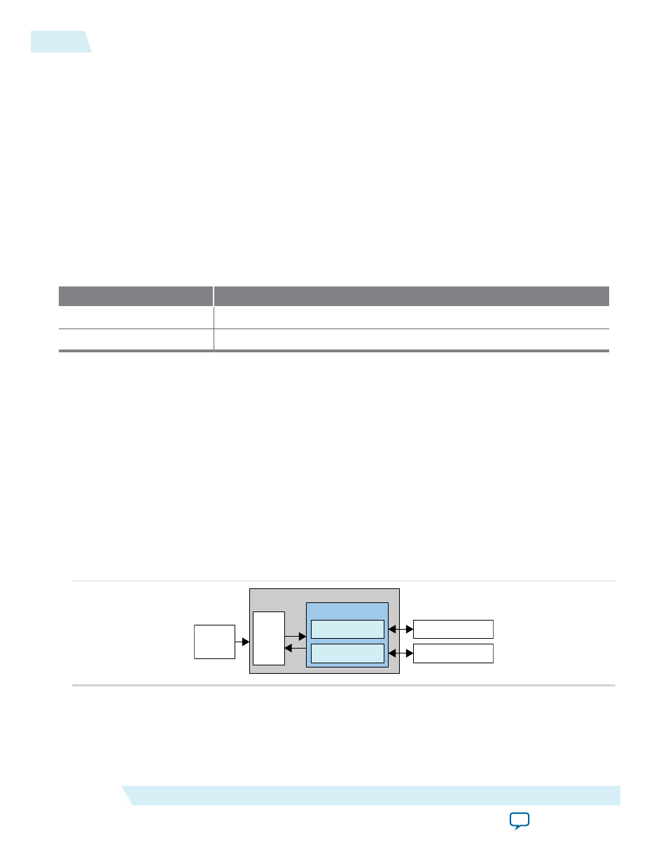
Figure 2-5: Power Management Controller Architecture
I/O Power Down
Global Clock Gating
Sleep Mode
Finite
State
Machine
Internal
Oscillator
Power Management Controller
I/O Buffer
Global Clock Network
MAX 10 device contains hardware features that enable I/O power down and global clock (GCLK) gating
to manage low-power state during sleep mode. You can power down the I/O buffer dynamically when
your application is in idle or sleep mode. One example is the digital single lens reflex DSLR camera
2-6
Instant-On Support
UG-M10PWR
2015.02.09
Altera Corporation
MAX 10 Power Management Features and Architecture