Altera MAX 10 Power User Manual
Page 8
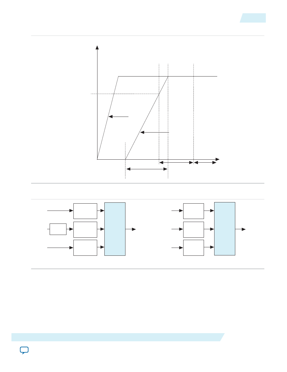
Figure 2-3: Relationship Between t
RAMP
and POR Delay
Time
POR trip level
Volts
POR delay
configuration
time
tRAMP
first power
supply
last power
supply
Figure 2-4: Simplified POR Diagram for MAX 10 Devices
VCCIO
Modular
Main POR
Main POR
VCCA
VCCIO POR
VCC
VCC POR
VCCA POR
VCCIO
Modular
Main POR
Main POR
VCCA
VCCIO POR
VCC_ONE
VCC POR
VCCA POR
Voltage
Regulator
Single Supply Device
Dual Supply Device
After the MAX 10 device enters user mode, the POR circuit continues to monitor the V
CCA
and V
CC
power supplies. This is to detect a brown-out condition during user mode. If either the V
CCA
or V
CC
voltages go below the POR trip point during user mode, the main POR signal is asserted. When the main
POR signal is asserted, the device is forced into reset state. V
CCIO
(3)
is monitored by the POR circuitry. In
the event of the V
CCIO
(3)
voltage drops during user mode, the POR circuit does not reset the device.
However, if you are using instant-on features, the POR circuit does monitor the VCCIO voltage drop for
up to 9 ms after the last power rail reaches its trip point.
UG-M10PWR
2015.02.09
Power Supplies Monitored and Not Monitored by the POR Circuitry
2-5
MAX 10 Power Management Features and Architecture
Altera Corporation