Wiring, General wiring guidelines, Mechanical connection of the base modules – Pilz PSSu E PS-P 5V User Manual
Page 23: 6wiring, 1 general wiring guidelines, 1 mechanical connection of the base modules
Pilz GmbH & Co. KG, Felix-Wankel-Straße 2, 73760 Ostfildern, Germany
Telephone: +49 711 3409-0, Telefax: +49 711 3409-133, E-Mail: [email protected]
6-1
6.1
General wiring guidelines
6
Wiring
6
6000
Wiring
Wiring
6-
6.1
General wiring guidelines
6100
General wiring guidelines
6-
][Verdrahtung BA Einleitung
Please note:
][Verdrahtung Netzteil
Safe electrical isolation must be ensured for the external supplies.
Failure to do so could result in electric shock.
Use copper wiring.
][Verdrahtung Zusatz mit C
The terminal configuration as stated on the front plate applies for base
modules with C-rail. The terminal configuration as stated in the tech-
nical documentation applies for all other base modules.
6.1.1
Mechanical connection of the base modules
Mechanical connection of the base modules
6-
][Modulverdrahtung mech
Procedure:
Use a flat blade screwdriver (DIN 5264-A)!
Strip the wire back 8 mm.
If necessary, label the connection level with a colour marker [3].
Base module with screw terminals:
– Use a screwdriver to loosen the screw on the screw terminal [1]
– Insert the stripped cable into the round fixing hole [2], as far as it
will go.
– Tighten up the screw on the screw terminal.
– Check that the cable is firmly seated.
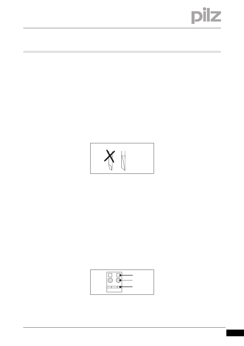
Base module with cage clamp terminals:
– Insert the screwdriver [4] into the square hole [1].
– Insert the stripped cable into the round fixing hole [2], as far as it
will go [5].
– Pull out the screwdriver [6].
– Check that the cable is firmly seated.
DIN 5264-A
21
11
[1]
[3]
[2]