Wiring, General wiring guidelines, Mechanical connection of the base modules – Pilz PSSu E PD1 User Manual
Page 21: 6wiring, 1 general wiring guidelines, 1 mechanical connection of the base modules
Pilz GmbH & Co. KG, Felix-Wankel-Straße 2, 73760 Ostfildern, Germany
Telephone: +49 711 3409-0, Telefax: +49 711 3409-133, E-Mail: [email protected]
6-1
6.1
General wiring guidelines
6
Wiring
6
6000
Wiring
Wiring
6-
6.1
General wiring guidelines
6100
General wiring guidelines
6-
][Verdrahtung BA Einleitung
Please note:
][Verdrahtung PD1
Safe electrical isolation must be ensured for the external supplies.
Failure to do so could result in electric shock.
The external power supplies must comply with the current applicable
standard EN 60950-1, EN 61140, EN 50178 or EN 61558-1.
The maximum current load on the connection terminals is 4 A per
supply.
Permitted infeed at the module's connection terminals:
– PE
– 0 V
– Shield
– - 30 VDC ... + 30 VDC
– - 48 VAC ... + 48 VAC
Use copper wiring.
][Verdrahtung Zusatz ohne C
The terminal configuration as stated on the front plate applies for base
modules without C-rail. The terminal configuration as stated in the
technical documentation applies for all other base modules.
6.1.1
Mechanical connection of the base modules
Mechanical connection of the base modules
6-
][Modulverdrahtung mech
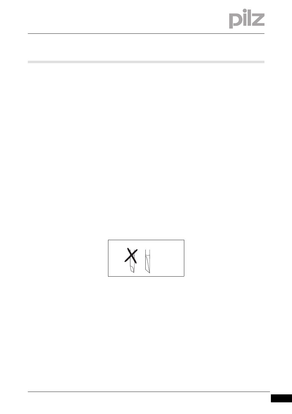
Procedure:
Use a flat blade screwdriver (DIN 5264-A)!
Strip the wire back 8 mm.
If necessary, label the connection level with a colour marker [3].
Base module with screw terminals:
– Use a screwdriver to loosen the screw on the screw terminal [1]
– Insert the stripped cable into the round fixing hole [2], as far as it
will go.
– Tighten up the screw on the screw terminal.
– Check that the cable is firmly seated.
DIN 5264-A