2 integrated protection mechanisms, 3 reaction times, Integrated protection mechanisms – Pilz PSSu E S 4DI-D User Manual
Page 13: Reaction times
Function description
Operating Manual PSSu E S 4DI-D
1001322-EN-04
13
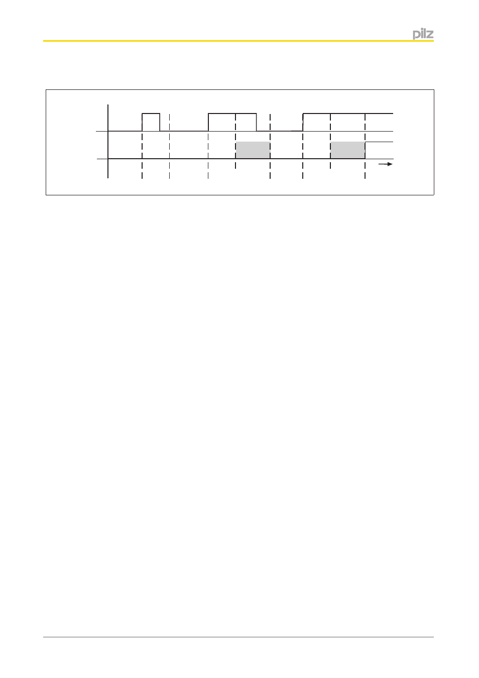
Timing diagram
Input
PII
t
2
+t
3
t
t
1
t
1
t
2
+t
3
t
1
}
Input: Signal at the input
}
PII: Status of process image (PII)
}
t
1
Minimum processing time (see Technical details)
}
t
2
Maximum processing time (see Technical details)
}
t
3
Cycle time of module bus
Shaded area: Status of process image (PII) undefined.
Integrated protection mechanisms
When the PSSu E F PS1(-T) is used to supply the system, the module supply is buffered
for 20 ms if the supply voltage is interrupted.
The module provides the following diagnostic data:
}
Start-up error
}
Configuration error
}
ST communication error
}
Bus termination error
}
Output overload
}
Temperature error: too warm
}
Temperature error: too hot
Reaction times
Information on the reaction times of the inputs can be found in the PSSuniversal System
Description.
4.1.2
4.1.3
- PSEN in1p (16 pages)
- PSEN in1n (12 pages)
- PSEN rs2.0-300 (16 pages)
- PSEN rs1.0-175 (16 pages)
- PSEN enc m1 eCAM (46 pages)
- PSENme 1S / 1AS (16 pages)
- PSENme 1S / 1AS (6 pages)
- PSENme 2 / 2A (6 pages)
- PSENme 4 / 4A (5 pages)
- PSEN 1.1b-25/PSEN1.1-20/8mm/10m/EX/1unit (8 pages)
- PSEN 1.1p-22/PSEN 1.1-20/8mm/ix1/ 1unit (6 pages)
- PSEN 1.1-10 / 1 actuator (6 pages)
- PSEN 1.2p-20/PSEN 1.2-20/8mm/ 1unit (6 pages)
- PSEN 1.1p-23/PSEN 1.1-20/8mm/ATEX/ 1unit (8 pages)
- PNOZ m EF 2MM (6 pages)
- PSEN 1.2p-22/PSEN 1.2-20/8mm/ix1/ 1unit (6 pages)
- PSEN 1.1p-25/PSEN 1.1-20/8mm/ATEX/ix1 (8 pages)
- PSEN 1.1-10 / 1 actuator (6 pages)
- PSEN 1.2p-23/PSEN 1.2-20/8mm/ATEX/ 1unit (8 pages)
- PSEN 1.1a-20/PSEN 1.1-20 /8mm/5m/1unit (6 pages)
- PSEN 1.2p-25/PSEN 1.2-20/8mm/ATEX/ix1 (8 pages)
- PSEN 1.1a-22/PSEN 1.1-20 /8mm/5m/ix1/1un (6 pages)
- PNOZ m EF 2MM (6 pages)
- PNOZ m EF 2MM (6 pages)
- PSEN 1.1b-23/PSEN1.1-20/8mm/10m/EX/1unit (8 pages)
- PNOZ m EF 2MM (8 pages)
- PSEN 1.1p-20/PSEN 1.1-20/8mm/ 1unit (6 pages)
- PSEN 1.1p-29/PSEN 1.1-20/7mm/ix1/ 1unit (6 pages)
- PSEN ma1.3a-20/PSEN ma1.3-08/8mm/1unit (10 pages)
- PSEN ma1.3a-22/PSEN ma1.3-08/8mm/1unit (10 pages)
- PSEN ma1.3b-23/PSEN ma1.3-08/8mm/1unit (10 pages)
- PSEN ma1.3b-25/PSEN ma1.3-08/8mm/1unit (10 pages)
- PSEN ma1.3p-20/PSEN ma1.3-08/8mm/1unit (10 pages)
- PSEN ma1.3p-22/PSEN ma1.3-08/8mm/ix1/1un (10 pages)
- PSEN ma1.3n-20/PSEN ma1.3-08/8mm/1unit (12 pages)
- PSEN ma1.3-20 M12/8-0.15m 1switch (10 pages)
- PSEN ma1.4p-52/PSEN ma1.4-03mm/ 1unit (10 pages)
- PSEN ma1.4p-51/PSEN ma1.4-03mm/ 1unit (10 pages)
- PSEN ma1.4n-51/ 1switch (9 pages)
- PSEN ma1.4n-50/PSEN ma1.4-03mm/ 1unit (10 pages)
- PSEN ma1.4-51 M12/8-0.15m 1switch (10 pages)
- PSEN ma1.4p-57/PSEN ma1.4-10mm/ 1unit (10 pages)
- PSEN ma1.4a-52/PSEN ma1.4-03mm/ 1unit (10 pages)
- PSEN ma1.4a-51/PSEN ma1.4-10mm/ 1unit (10 pages)
- PSEN ma1.4p-50/PSEN ma1.4-03mm/ 1unit (10 pages)