4 summary and overview, 5 pssu assignment in system environment a, 1 addresses in the process image – Pilz PSSu E S 2AO U User Manual
Page 18: Summary and overview, Pssu assignment in system environment a, Addresses in the process image
Function description
Operating Manual PSSu E S 2AO U(T)
21423EN03
18
}
Switchon value 1 corresponds to 26 214
–
Switchon value 2 corresponds to 16 384
The relationship between the switchon value and the actual voltage at the output is not de
pendent on the data format, but is dependent on the scaling. The module sets the voltage,
which corresponds to the switchon voltage after scaling. Please refer to the "Scaling" sec
tion in this manual.
4.2.4
Summary and overview
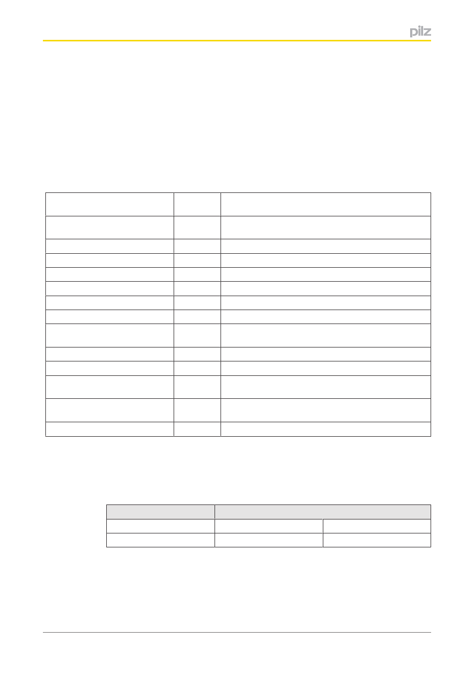
The module has the following configuration options:
Default
value
Key
Output range
0
0 V ... 10 V
(1 = 10 V ... 10 V)
Manufacturer scaling active
1/TRUE
Activated
Manufacturer scaling offset
0
Offset: Magnitude 0
Manufacturer scaling gain
32
D
Amplification by 1/8, displaced three bit places
User scaling active
0/FALSE
deactivated
User scaling offset
0
Offset: Magnitude 0
User scaling gain
256
D
1x amplification, signal unchanged
Switchon value active
0
Manufacturer switchon value active
(1/TRUE = User switchon value active)
Manufacturer switchon value
0
0 V on switchon
User switchon value
0
0 V on switchon
Sign and magnitude representa
tion active
0/FALSE
Deactivated; two's complement is activated
Formation of magnitude active
0/FALSE
Deactivated
(1/TRUE = Activated, not with output range 10 V ... 10 V)
Output DAC raw value only
0/FALSE
deactivated
4.2.5
PSSu assignment in system environment A
4.2.5.1
Addresses in the process image
Each output channel occupies 16 consecutive bit addresses for the output data.
Configuration
Standard bus system
STPII
STPIO
None
32 Bit