Pilz PNOZ e7p 24VDC 2 so User Manual
Page 3
- 3 -
Funktionen
• Wird an den Eingang Y5 für mindestens
250 ms ein High-Signal (+24 V DC) gelegt,
wechselt der Ausgang Y32 in die
Diagnosefunktion. Die Ansteuerung
erfolgt über einen Treiber, der als Zubehör
zur Verfügung steht oder selbst erstellt
werden kann. Ist der Eingang Y5 offen
oder Low, funktioniert Y32 wie ein
Hilfsausgang.
• Zur logischen Verknüpfung mehrerer
Geräte besitzt das PNOZ e7p einen
UND- Eingang (S36). Der Eingang weist
eine Schaltverzögerung auf. Werden
mehrere Geräte UND-verknüpft, addiert
sich diese Verzögerungszeit.
Betriebsarten
• Einkanaliger Betrieb in allen Betriebsar-
ten: Eingangsbeschaltung nach
EN 60204, keine Redundanz im Eingangs-
kreis; Erdschlüsse im Tasterkreis werden
erkannt.
• Betriebsart 1: Einzelauswertung der
Eingangskreise S12 und S22. Der
Eingangskreis S12 wirkt auf Sicherheits-
ausgang 14, der Eingangskreis S22 auf
Sicherheitsausgang 24.
• Betriebsart 2: Die Eingangskreise S12
und S22 sind UND-verknüpft. Das
Ergebnis der Verknüpfung wirkt auf die
Sicherheitsausgänge 14 und 24.
• Automatischer Start: Gerät ist aktiv,
sobald der Eingangskreis geschlossen ist.
• Überwachter Start: Gerät ist erst aktiv,
wenn bei geschlossenem Einganskreis der
Starttaster betätigt und wieder losgelassen
wurde.
• Kontaktvervielfachung und -verstärkung
durch Anschluss eines Kontaktblocks
(z. B. PZE X4.1P) oder von externen
Schützen.
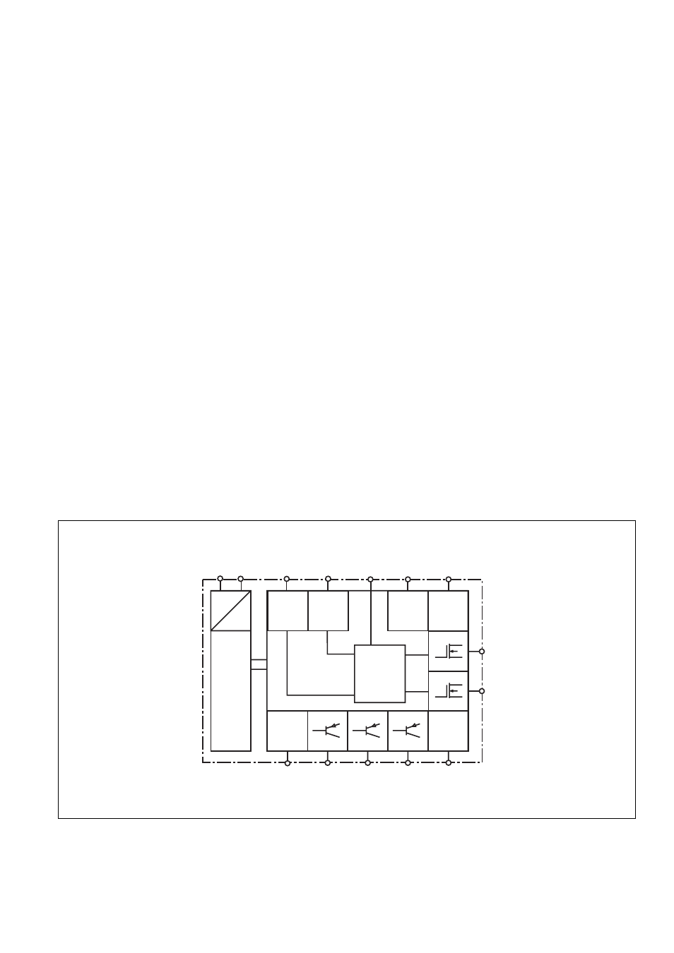
Innenschaltbild
Internal wiring diagram
Schéma interne
Input
S12
S22
U
B
=
=
A1 A2
Power
Diag-
nostic
Y5
Input
Reset/
Start
S34
S11
S21
Y32
Feed-
back
Y6
Feed-
back
Y7
14
24
S36
+
-
Logic
Functions
• If there is a high signal (+24 VDC) at input
Y5 for at least 250 ms, output Y32
switches to diagnostic mode. This is
controlled via a driver, which is available
as an accessory or which you can create
yourself. If input Y5 is open or low, Y32 will
operate as an auxiliary output.
• The PNOZ e7p has an AND input (S36)
for logic connections between several
units. The input has a switch delay. If
several units are AND-linked, this delay
time is added together.
Operating modes
• Single-channel operation in all
operating modes: Input wiring in
accordance with EN 60204, no redun-
dancy in the input circuit; earth faults in the
pushbutton circuit are detected.
• Operating mode 1: Individual evaluation
of input circuits S12 and S22. Input circuit
S12 affects safety output 14, input circuit
S22 affects safety output 24.
• Operating mode 2: Input circuits S12 and
S22 are AND-linked. The result of the logic
operation affects safety outputs 14 and 24.
• Automatic reset: Unit is active as soon as
the input circuit is closed.
• Monitored reset: Unit is not active until
the input circuit is closed and the reset
button has been operated and then
released.
• Increase in the number of safety
contacts available by connecting a
contact block (e.g. PZE X4.1P) or external
contactors.
Fonctions
• Si un niveau haut (+24 V CC) est appliqué
sur l’entrée Y5 pendant au moins 250 ms,
la sortie Y32 commute en sortie de
diagnostic. La commande s’effectue par
le biais d’un protocole, disponible en tant
qu’accessoire ou programmable par
l’utilisateur. Si l’entrée Y5 est ouverte ou
en niveau bas, Y32 fonctionne comme une
sortie d’information.
• Pour le couplage logique de plusieurs
appareils, le PNOZ e7p possède une
entrée ET (S36). L’entrée est temporisée
à l’enclenchement. Si plusieurs appareils
sont couplés en ET logique, les durées de
temporisations se cumulent.
Modes de fonctionnement
• Fonctionnement à 1 canal dans tous les
modes de fonctionnement : câblage des
entrées selon l’EN 60204, pas de redon-
dance sur le circuit d’entrée ; la mise à la
terre du circuit d’entrée est détectée.
• Mode de fonctionnement 1 : Analyse
individuelle des circuits d’entrée S12 et
S22. Le circuit d’entrée S12 agit sur la
sortie de sécurité 14, le circuit d’entrée
S22 sur la sortie de sécurité 24.
• Mode de fonctionnement 2 : Les circuits
d’entrée S12 et S22 ont une liaison ET. Le
résultat de la liaison agit sur les sorties de
sécurité 14 et 24.
• Réarmement automatique : L’appareil
est actif dès que le circuit d’entrée est
fermé.
• Réarmement auto-contrôlé : L’appareil
est uniquement actif lorsque le circuit
d’entrée est fermé et que le poussoir de
réarmement a été actionné puis relâché.
• Multiplication et amplification des
contacts par raccordement d’un bloc de
contacts (par exemple, PZE X4.1P) ou de
contacteurs externes.