Block diagram/terminal configuration, Function description – Pilz PZE X4V 8/24VDC 4n/o User Manual
Page 6
PZE X4V8
Operating Manual PZE X4V8
1003204EN05
6
}
Earth fault in the input circuit:
The output relays deenergise and the safety contacts open.
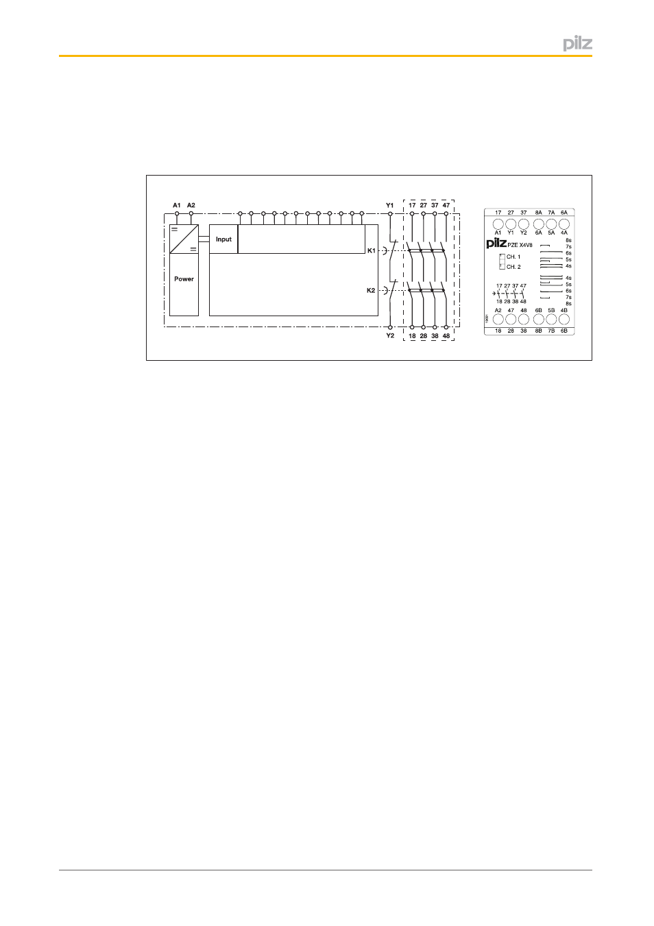
Block diagram/terminal configuration
8A
8B
4A
7B
5A
6A
6A
7A
Delay
*
6B
6B
5B 4B
*Insulation between the nonmarked area and the relay contacts: Basic insulation (over
voltage category III), Protective separation (overvoltage category II)
Function description
The contact expansion module is an addon device with selectable delayon deenergisa
tion, and it is used to expand a safety circuit. The contact expansion module is driven by a
base unit (e. g. emergency stop relay).
}
Functional procedure after closing the safety contacts of the base unit:
–
The supply voltage is present at the input (A1) of the contact expansion module.
–
Close the safety contacts 1718, 2728, 3738 and 4748.
–
The LEDs "CH. 1" and "CH. 2" are lit.
}
Functional procedure after opening the safety contacts of the base unit:
–
There is not supply voltage at input (A1) of the contact expansion module.
–
Safety contacts 1718, 2728, 3738 and 4748 open after the delay time.
–
The LEDs "CH. 1" and "CH. 2" go out.