Pilz PZE 9 24VAC 8n/o 1n/c User Manual
Page 3
- 3 -
Mise en oeuvre
Remarques préliminaires :
• Installez des fusibles (caractéristique
techniques) en amont des contacts
de sortie pour éviter leur soudage.
• Calcul de la longueur maximale de
conducteur I
max
sur le circuit d’entrée et la
boucle de retour :
R
lmax
R
l
/ km
I
max
=
R
lmax
= résistance max. totale du câble
(voir les caractéristiques techniques)
R
l
/km = résistance du câble/km
• Pour les appareils en AC une liaison
amovible entre le boîtier et la terre
est exigée.
• Ne pas commuter de faibles intensités
(ex. 30 mA) par des contacts ayant au
préalable commutés des intensités plus
élevées
• Le contact 91-92 est un contact
d'information (ex. : affichage). Ne pas
utiliser dans le circuit de sécurité
• Les relais internes du PZE 9 ne doivent
être alimentés que par la tension interne
du boîtier ou une alimentation (24 VDC)
protégée contre les courts-circuits.
• Utiliser uniquement des fils de cablâge
en cuivre 60/75 °C.
• Le couple de serrage sur les bornes de
racordement ne doît pas dépasser
0,8 Nm.
• Respectez les données indiquées dans
les caractéristiques techniques
Branchement
• Relier la borne de terre (uniquement
appareils en AC).
• Amener la tension d'alimentation (A1-
A2).
• Circuit d'entrée
- commande par 1 canal :
câbler le contact sur K1 et U1 ;
ponter K1-K2 et Y3-Y4.
- comande en 2 canaux sans détection
des courts-circuits:
câbler les contacts sur K1, U1 et
K2, U2; ponter Y3-Y4
- comande en 2 canaux avec détection
des courts-circuits:
câbler les contacts sur K1, U1 et
Y3, Y4; ponter K2-U2
• Boucle de retour
Relier les bornes Y1 et Y2 avec la
boucle de retour de l'appareil de base
Operation
Please note for operation:
• To prevent a welding together of the
contacts, a fuse ( technical data )
must be connected before the output
contacts.
• Calculating the max. cable runs I
max
at the
input and feedback circuit:
R
lmax
R
l
/ km
I
max
=
R
lmax
= max. overall cable
resistance (see Technical details)
R
l
/km = cable resistance/km
• With AC units a detachable connection
is required between unit and system
earth.
• Low currents (e.g. 30 mA) should not be
switched across contacts across which
high currents have previously been
switched.
• Auxilliary contact 91-92 is not to be used
for safety circuits
• Only run the relays of the contact block
using the units own, or a short-circuit
proof, voltage supply (24 VDC).
• Use copper wiring that will withstand
60/75 °C
• Tighten terminals to 0.8 Nm.
• Important details in the section
"Technical Data" should be noted and
adhered to.
Connection
• Connect the operating earth (AC units
only)
• Connect the operating voltage between
A1i(+) and A2 (-).
• Input circuit
- Single channel operation:
Connect the safety contacts to K1 and
U1; bridge K1-K2 and Y3-Y4.
- Two channel operation without short-
circuit recognition:
Connect the safety contacts to K1, U1
and K2, U2; bridge Y3-Y4.
- Two channel operation with short-circuit
recognition:
Connect the safety contacts to K1, U1
and Y3, Y4; bridge K2-U2.
• Feedback control loop
Connect terminals Y1 and Y2 with the
feedback control loop of the base unit.
Inbetriebnahme
Beachten Sie bei der Inbetriebnahme:
• Vor die Ausgangskontakte eine
Sicherung ( technische Daten)
schalten, um das Verschweißen der
Kontakte zu verhindern.
• Berechnung der max. Leitungslänge I
max
am Eingangs- und Rückführkreis:
R
lmax
R
l
/ km
I
max
=
R
lmax
= max. Gesamtleitungs-
widerstand (s. technische Daten)
R
l
/km = Leitungswiderstand/km
• Bei AC-Geräten ist eine lösbare
Verbindung zwischen Gerät und
Betriebserde ist erforderlich.
• Keine kleinen Ströme (z. B. 30 mA) mit
Kontakten schalten, über die zuvor große
Ströme geführt wurden.
• Hilfskontakt 91-92 nicht für Sicherheits-
stromkreise verwenden!
• Relais des Kontaktblockes nur mit der
geräteeigenen oder einer kurzschluß-
festen Spannungsversorgung (24 V DC)
betreiben.
• Leitungsmaterial aus Kupferdraht mit
einer Temperaturbeständigkeit von 60/
75 °C verwenden.
• Das Anzugsdrehmoment der Schrauben
auf den Anschlußklemmen darf max.
0,8 Nm betragen.
• Angaben im Kapitel "Technische Daten"
unbedingt einhalten.
Anschluß
• Bei AC-Geräten Betriebserde anschlie-
ßen.
• Versorgungsspannung an Klemmen A1
(+) und A2 (-) anschließen.
• Eingangskreis
- Einkanalige Ansteuerung:
Sicherheitskontakt an K1 und U1
anschließen; Brücke zwischen K1-K2
und Y3-Y4.
- Zweikanalige Ansteuerung ohne Quer-
schlußerkennung:
Sicherheitskontakte an K1 und U1 und
an K2 und U2 anschließen, Brücke
zwischen Y3-Y4
- Zweikanalige Ansteuerung mit Quer-
schlußerkennung:
Sicherheitskontakte an K1 und U1 und
an Y3 und Y4 anschließen, Brücke
zwischen K2-U2
• Rückführkreis
Klemmen Y1 und Y2 mit dem Rückführ-
kreis des Grundgerätes verbinden.
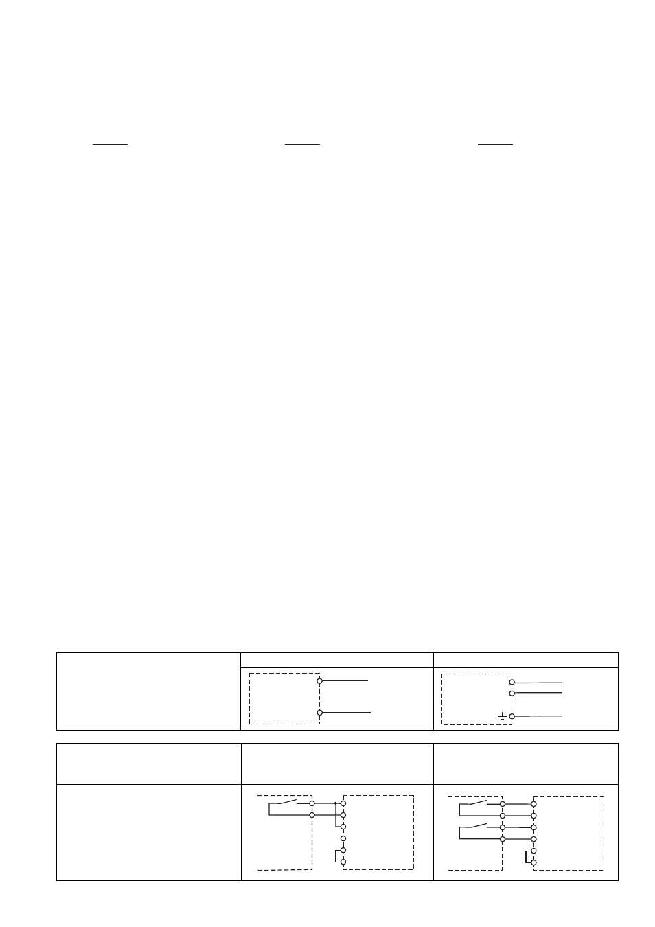
Versorgungsspannung/
Supply voltage/Tension d’alimentation
AC
DC
Eingangskreis/
Input circuit/Circuit d’entrée
K1
K2
U1
Y4
Y3
PZE
U2
K1
K2
U1
Y4
Y3
PZE
U2
Einkanalige Ansteuerung
Single Channel control
Commande par un canal
Zweikanalige Ansteuerung
Two channel control
Commande par deux canaux
ohne Querschlußerkennung
without short-circuit recognition
sans détection des courts-circuits
A1
L+
A2
L-
A1
L1
N
A2
PE