Woodhaven 3400-3440: Scarfing Sleds User Manual
Page 5
11
10
4
10
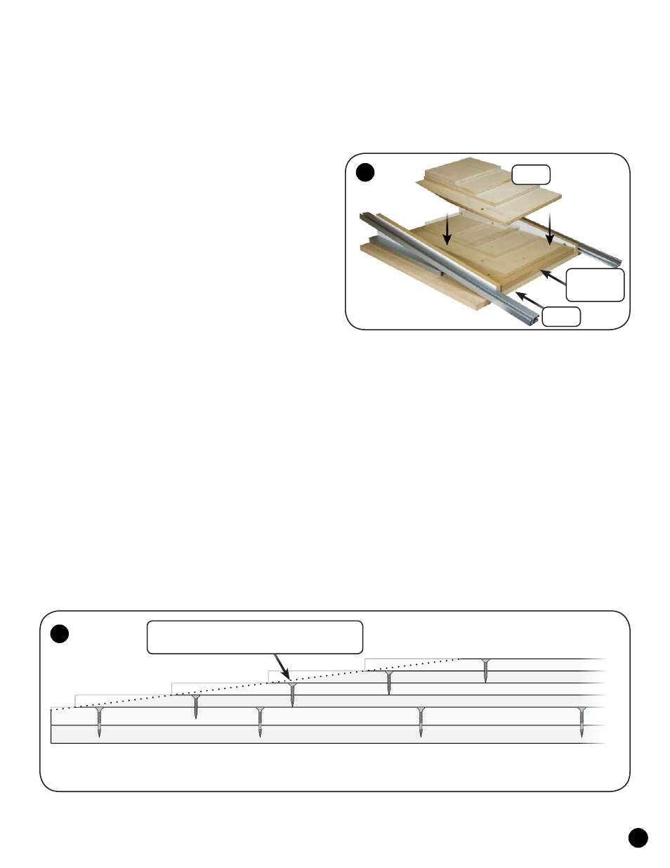
Work
Base
Sacrifi cial
Plate
ASSEMBLY - ATTACH SACRIFICIAL PLATE TO BASE
Make sure the base is on a flat solid support when per-
forming these operations.
Cut a sacrificial plate out of 3/4" thick flat sheet stock such
as MDF or particle board. The plate should measure at least
8" wide (or up to 24" - the width of the base) by the length
between the Angle Guides. Position the plate flush with the
front edge of the base at the narrow end of the Angle Guides.
Drill and countersink the plate for flat head wood screws (not
included) and place the screws at least 2-3" back from the front
edge of the base so the router bit will not strike them. Use addi-
tional screws as needed to fasten the plate tight to the base. This
sacrificial plate will need to be replaced periodically. See fig.
10 & 11.
MOUNT WORK TO THE BASE
Make sure the base is on a flat solid support when per-
forming these operations.
The thickness capacity of the Scarfing Jig depends on the
Angle Guide selected. Thickness capacity for the 8-1 Angle
Guide is 2-3/8", 10-1 Angle Guide is 1-7/8" and the 12-1 Angle
Guide is 1-5/8".
It is necessary to mount the work to the sacrificial plate,
and then to each other. The work pieces must be stair stepped
when attaching them. We recommend you use flat head wood
screws to hold the work securely, but you may also be able to
use double stick tape or other holding methods. See fig. 10 &
11.
The amount of stair step will vary depending on the thick-
ness of the work and the ratio of the Angle Guides, but the first
work piece should always be attached 1" back from the front
edge of the base/plate. See fig. 10 & 11.
To figure the amount of stair step, multiply the thickness
of the work (6mm, 1/4", 12mm, 1/2", etc.) by the ratio of the
Angle Guide. For example, using 12mm stock with the 8-1 ratio
Angle Guide, the formula would be: 12mm x 8 = 96mm stair
step. Attach each work piece separately. Make sure you place
the screws at least one inch back from the area of the stair step
so the router bit can't strike them. See fig. 10 & 11.
Long parts will require extra support along the length of
the part to keep it on a flat and even plane. This could be as
simple as 2 x 4's placed under the part at even intervals.
Screws need to be positioned so they don't
interfere with the eventual cut line of the bit.