Woodhaven 3400-3440: Scarfing Sleds User Manual
Page 2
BEFORE BEGINNING
Identify and verify that you have all the parts listed. You'll
need a 1/4" drill, 1/2" countersink, a 7/16" wrench and a #3
Phillips screwdriver for assembly. You will also need to sup-
ply material for a mounting base (see instructions) to mount the
Scarfing Sled to and a flat work surface on which to use it. Read
the instructions carefully before beginning.
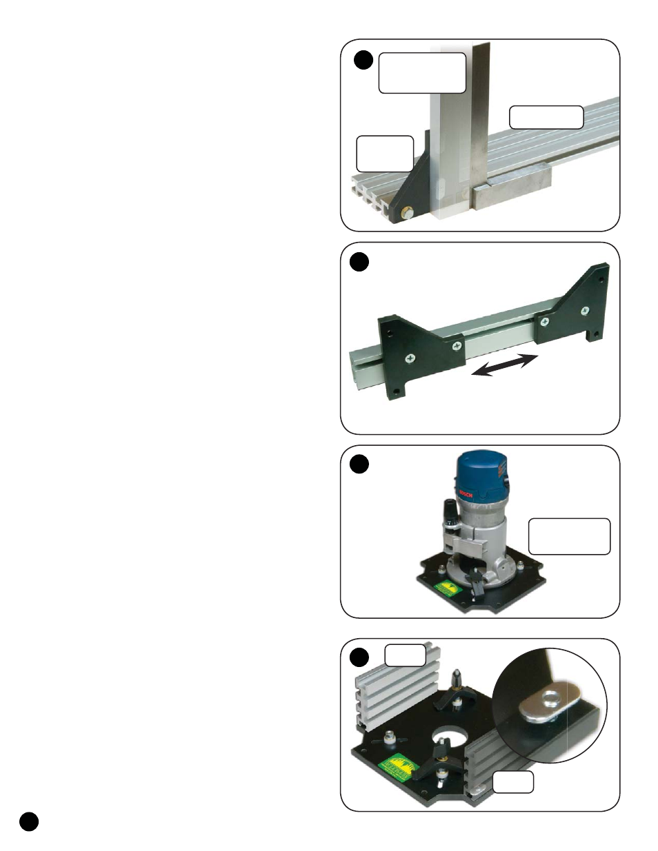
ASSEMBLY - TRACK SLED
Install a washer (WB002) on the eight 3/4" bolts (HB020).
In the Brackets (3400B - 4 pieces, 2 pairs), insert the bolts from
the opposite side of the countersunk holes, through the non-
countersunk holes. Start an oval nut (5760B - flat side first) on
the end of each bolt. With the Ultra Track (4424, 4436, 4448,
4460 or 4472 depending on model purchased) laying on its 3"
face on a flat surface, mount a pair of Brackets to each Ultra
Track. The angled end of each Bracket should be next to the end
of the Ultra Track. Slide the Bracket into the T-slot of the Ultra
Track, position each Bracket flush with the end and edge of the
Ultra Track, then tighten the bolts. See fig. 1.
Insert the 3/4" flat head screws (MF010) in the counter-
sunk holes in the Brackets and start an oval nut (5760B - flat
side first) on the end of each screw. Remove the paper back-
ing and install two glide pads (PAD1 - 8 total), on each end of
both Double Tracks (4012). With one of the Ultra Tracks laying
on its 3" face on a flat surface, slide a 12" Double Track on to
the oval nuts on each bracket. Check that the Double Track is
square to the Ultra Track and flush with the upright edge of
the Bracket, then tighten the screws. Flip the assembly 90º so
it setting on the Double Tracks and attach the remaining Ultra
Track/Brackets to the opposite end of the Double Tracks. Space
the inside ends of the Brackets 3-5/8" apart for now and tighten
the screws. This completes what will now be referred to as the
Track Sled. See fig. 1 & 2.
ASSEMBLY - ROUTER PLATE
Follow the directions in the 4973 Plate Hardware and
attach your router to the Router Plate (3000P). The router does
not need to be perfectly centered on the plate. You can use a
plunge or standard base router. Position your router on the plate
so the router handles (if you haven't removed them) are parallel
to one of the router plate edges and position the router to take
the best advantage of the plates mounting slots and router con-
trol locations. Mark the position of the router on the router plate
with a timing mark so you can return it to the same location,
then temporarily remove the router. See fig. 3.
An optional drill style plate (PN 3000PD) is available for
semi-permanent mounting of your router, but it requires drilling
mounting holes in the plate.
Select the mounting locations for the 6" Ultra Tracks on
the router plate. The Ultra Tracks mount on opposite sides from
each other and parallel to the router handles. From the underside
of the router plate insert the 5/8" flat head screws (MF006) in
the four selected countersunk holes. Start an oval nut (5760B -
flat side first) on the end of each screw. Slide a 6" Ultra Track
(4406) on to two of the oval nuts, position it flush with the
router plate at it's ends and edge, then tighten the screws. Repeat
for the second Ultra Track on the opposite side. See fig. 4.
1
3
4
2
1
Ultra Track
3400B
Bracket
3000P
Router Plate
4406
4406
4012
Double Track
2
Space brackets
3-5/8" apart.